This is the Petoi product documentation hub. We keep fast iteration on our models and codes to bring bionic robotic pets to the world. Please read the notes regarding versions carefully to configure your robot.
After you’ve assembled a Petoi robot or have bought a pre-assembled version, the following steps are recommended:
Play with the default actions
Play with simple joint control
Note that all the tutorials work on Bittle/Bittle X robot dogs and Nybble robot cat even though we use one particular robot pet as an example.
FAQ
Question: I am confused by the product packaging and unsure if you sent me the right robot.
Answer: We reuse the packaging for Bittle and BIttle X. If you order a Bittle but receive a package with “Bittle X” marking, or vice versa, you can check the text label with the barcode. That text identifies what’s inside the packaging.
Check on our official website or in the Petoi Doc Center.
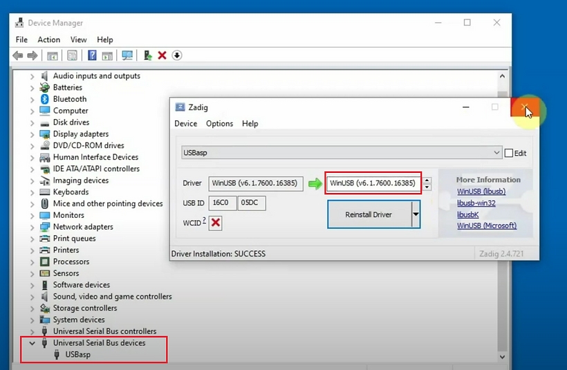
When you use a USB uploader to upload the firmware for the NyBoard, if there is no serial port in the port list of Device Manager.
please download and install the driver:
Mac:
Windows:
Linux:
BiBoard
When you use a USB type-C data cable to upload the firmware for the BiBoard, if there is no serial port in the port list of Device Manager.
please download and install the driver:
For more details, please refer to .
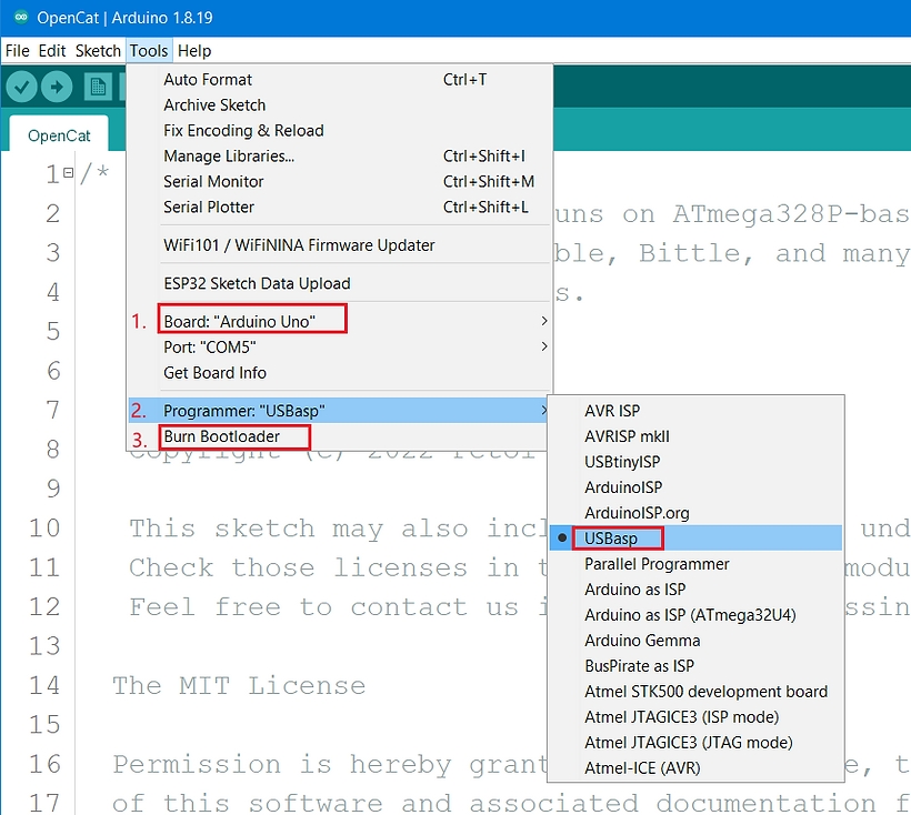
Upload the firmware
There are two methods to Upload the firmware to the robot:
The simplest method is to use the . No programming is involved. You can play with some preset modes.
If you have some programming experience, you can use the You will be able to modify the open-source codes for your new projects.
If you are using NyBoard, please refer to
If you have a NyBoard(with Bittle and Nybble), we highly recommend using the green USB programmer to upload the firmware. The Bluetooth dongle is not as stable and may cause the mainboard's bootloader to crash if interrupted in the middle.
For BiBoard(with Bittile X), the USB/Bluetooth connections are built on the board already.
Petoi robot joint index
We humans and many other legged animals have many joints. They give us the freedom to move in many ways. Though it's difficult to reproduce those complex motions on a robot, we can simplify all those joints to limited numbers of actuators.
When controlling so many joints, the first thing is to index them. We can define an order according to their distance from the torso. For example, the shoulder joint is closer to the torso than the elbow joint, and the joint that let us look around is closer to the torso than the joint that let us nod. If we had tails, it would be as close as the head compared to the shoulder joints.
So we can order the joints in this way: head panning, head tilting, tail panning, tail tilting, 4x shoulder (or hip) roll, 4x shoulder (or hip) pitch, 4x elbows (or knees). For the joints in the same distance group, we can index them clockwise from the front-left corner if the body is looked at from behind.
And when we map those joints to a specific robot, the indexing becomes more practical. The ordering for the joint servo pins on NyBoard is like below:
NyBoard
BiBoard
Although the BiBoard has only 12 pins, the joint index numbers are configured in the same order as the NyBoard. The connection between the joint servo and the pin is shown in the figure below:
A servo plug has three wires. Plug it in the right direction or you may burn the chip. Thecolor of wires may vary for different models. However, the darkest-colored (Black or Brown) wire (GND for ground) is always the GND wire as a convention. The GND wire should be plugged closest to the board.
The index number of the joint servo has no corresponding relationship with the PWM pin number on the main board. You don't even need to read the pin numbers on the PCB board.
Coordinate values and directions
The rotation angle range of the joint servo is between [-125~125]. For the leg servo, when viewed from the left side of the robot, when the leg rotates counterclockwise from the 0-degree position around the joint center point (the screw fixing position), the angle is a positive value; clockwise rotation, the angle is a negative value; viewed from the right side of the robot, the leg rotation angle is mirror-symmetrical to the left side (when rotating clockwise from the 0-degree position around the joint center point, the angle is a positive value; Rotate counterclockwise, the angle is negative). For the robot's neck servo, looking down from the top of the robot's head, when the neck rotates counterclockwise from the position of 0 degrees around the joint center point (the position where the screw is fixed), the angle is a positive value; when it rotates clockwise, the angle is a negative value.
For the Nybble head servo (No. 1 servo) observed on the right side of the robot, the head rotates counterclockwise from the 0-degree position around the joint center point (screw fixed position), and the angle is positive; when it rotates clockwise, the angle is negative.
For the Nybble tail servo (No. 2 servo) facing the tail and looking down, the tail rotates counterclockwise from the 0-degree position around the center point (screw fixing position), and the angle is positive; when it rotates clockwise, the angle is negative.
This is a cool tutorial video made by one of our users, which briefs the process and explains its logic.
* The logic behind calibration is:
You don't know where the servos are pointing before they are powered and calibrated. So if you attach the legs, the legs will rotate to random angles and may collide with the robot's body or other legs and get stuck. If a servo is stuck for a long time, it may break.
The robot has a "calib" posture with all joints set at zero degrees. You can so that you know all the joints should be rotated to their zero points (though you cannot see because the legs are not attached to the servos yet). Then, you can attach the legs to the servos one joint by one joint, perpendicular to their nearby references on the body frame.
The principles are the same for Nybble and Bittle.
Prepare to Enter the Calibration State
Entering calibration mode requires the following preparations:
1. All servo circuits are connected to the motherboard
2. The battery is plugged into the controller board and is turned on (long-press the button on the battery to turn on/off the power)
3. The or is used to connect the robot to a computer or mobile phone
If you build the robot from an unassembled kit, do not install the head and leg components before entering the calibration state.
Enter the Calibration State
The robot's legs may point to unknown angles when booting up. When entering the calibration state, the joints will be moved to their zero positions. You can see the output gears of the servos rotate and then stop. Then, you can attach the legs and fine-tune the joint offsets in the software interface. There are 3 software interfaces to enter the calibration state and fine-tune the joints.
Use the Mobile App
Use
Use
You can also enter the calibration state by booting up the robot with one side up. This method doesn't require any computer, remote, or smartphone app, so it's convenient when you are focused on assembling the robot from the kit.
Install the screws
After completing the joint calibration, install the center screws to fix all the joint parts and servo gears.
Calibrator
Calibrate the joints
Nybble
Serial Monitor
Connect the USB Adapter
Connect the USB adapter to the mainboard and select the correct serial port. Please refer to the in the USB Uploader Module for specific steps.
You can choose the "Serial Monitor" in "Tools" menu bar, or click the button to open the serial monitor window:
4.Digital-Analog Converter
The usage of DAC
The purpose of the DAC is the opposite of that of the ADC. The DAC converts a digital signal into an analog signal for output.
Remember the music when NyBoard is turned on? It is using PWM to make music sound which uses high-speed switching to adjust the duty cycle to output voltage.
Compared with PWM, the DAC will directly output the voltage without calculating the duty cycle. ESP32 integrates a 2-channel 8-bit DAC with a value of 0-255. The voltage range is 0-3.3V. Therefore, the formula for calculating the output voltage of the DAC is as follows:
The demo is as follows:
6.Gyro IMU(MPU6050)
MPU6050 is the most widely used 6-axis gyroscope, which can not only measure 3-axis angular velocity and 3-axis acceleration more accurately, but also use the built-in digital motion processor (DMP) for hardware based attitude fusion calculation. So novices can use it very conveniently. For this reason, we also use MPU6050 gyroscope.
There are many demos of MPU6050 on Arduino UNO, the most famous is jrowberg's I2Cdev and MPU6050DMP library:
Unfortunately, this library cannot be run directly on BiBoard based on ESP32. We found the ported library on Github, which is easy to use. This library adds the definition of PGMSpace for the ARM and ESP series, adds the calibration function, and removes the FIFO overflow processing function (friends who are interested can use Beyond Compare for code comparison). The library contains I2Cdev and MPU6050, the address and compressed package are as follows:
After the download is complete, create a MPU6050 folder under Documents/Arduino/library, and copy the library files in the compressed package into it. The library of this modified MPU6050 is also compatible with ARM and AVR, so if you have the original I2Cdev and MPU6050 libraries in your computer, you can delete them.
Overview
At present, there are 3 versions of NyBoard: NyBoard V1_0, NyBoard V1_1 and NyBoard V1_2.
There are just a few differences between NyBoard V1_1 and NyBoard V1_2:
V1_2 has one NeoPixel LED attached to Pin D10.
Programmable Puppet Character
You may check a more detailed tutorial in the following post.
V1_2 supports both ATmega328p AU (bigger) and MU (smaller) chips.
Since the ESP8266 can be used as a regular Arduino board, we can write a simple Arduino code to open the serial port and send the serial commands to control the robot. It's like a stand-alone serial commander written in C and can go with the robot. You may write hundreds of pre-defined tasks without worrying about the memory limits on the main controller.
You can find a short test8266Master in OpenCat/ModuleTest:
void setup() {
// put your setup code here, to run once:
Serial.begin(115200);
Serial.setTimeout(5);
bool connected = false;
while (!connected) {
Serial.print("b 20 8 22 8 24 8");
for (byte t = 0; t < 100; t++) {
if (Serial.available())
if (Serial.read() == 'b') {
connected = true;
while (Serial.available() && Serial.read())
;
break;
}
delay(10);
}
delay(1000);
}
}
void sendCMD(const char cmd[], int wait = 0) {
Serial.print(cmd);
while (true) {
if (Serial.available() && toLowerCase(Serial.read()) == cmd[0]) {
delay(10);
while (Serial.available() && Serial.read())
;
break;
}
delay(2);
}
delay(wait);
}
void loop() {
sendCMD("d", 500); //rest and wait 0.5 seconds 趴下并等待0.5秒
sendCMD("khi"); //greetings 打招呼
sendCMD("kpu"); //pushups 俯卧撑
sendCMD("kvtF", 1000); //stepping 原地踏步
sendCMD("G"); //Turn off the gyro 关闭陀螺仪
sendCMD("kwkF", 1500); //walk 行走
sendCMD("kck"); //check 观察
sendCMD("kpu1"); //push ups with on hand 单手俯卧撑
sendCMD("kvtR", 2000); //spin 旋转
sendCMD("G", 100); //turn on the gyro 打开陀螺仪
sendCMD("ktrF", 1500); //trot 跑步
sendCMD("kjy", 0); //joy 加油
sendCMD("i 0 45 8 -90 9 -90", 1000); //rotate the head and arm joints 伸手转头
sendCMD("ksit", 1000); //sit 坐下
}
1.GPIO port
Operate the GPIO port of BiBoard
There is no separate GPIO port on BiBoard, but the multiplexed serial port 2 (pin 16, 17) or the PWM pin of the unused PWM servo interface can be used as GPIO port. The GPIO port is also relatively simple to use. After configuring the input and output mode, the usage is exactly the same as that of Arduino UNO. You can use any IO control program of Arduino UNO, just change the number of IO .
/* In this demo, we use TX2, RX2 as general purpose IO
* TX2 : IO17
* RX2 : IO16
*/
void setup() {
// initialize digital pin 16 & 17 as an output.
pinMode(16, OUTPUT);
pinMode(17, OUTPUT);
}
// the loop function runs over and over again forever
void loop() {
digitalWrite(16, HIGH); // GPIO 16 & 17 HIGH
digitalWrite(17, HIGH);
delay(1000); // wait for a second
digitalWrite(16, LOW); // GPIO 16 & 17 LOW
digitalWrite(17, LOW);
delay(1000); // wait for a second
}
2.Serial port
There are 2 serial ports,which are separately located on 2 expansion sockets (P16, P17) ,on BiBoard.
The serial port 1 on the P16 can be connected to the USB downloader and the external serial device. Please do not use the downloader and the external serial device at the same time. The serial port voltage division will lead to communication errors.
In the Arduino demo, Serial represents the serial port 0, Serial1 represents the serial port 1.Serial and Serial1 send to each other.
/* In this demo, we use Serial and Serial1
* Serial and Serial1 send to each other
*/
void setup() {
// initialize both serial ports:
Serial.begin(115200);
Serial1.begin(115200);
}
void loop() {
// read from port 1, send to port 0:
if (Serial1.available()) {
int inByte = Serial1.read();
Serial.write(inByte);
}
// read from port 0, send to port 1:
if (Serial.available()) {
int inByte = Serial.read();
Serial1.write(inByte);
}
}
Because the servo's gear teeth are discrete, aligning the legs to the right angles perfectly is impossible. So, you will need to fine-tune the offsets within the software.
The above interfaces will be displayed when you calibrate for the first time. You can also click to open the upper-right menu in the control panel and select Calibrate to re-access.
Prepare for calibration
Make sure you have uploaded the OpenCat Main function firmware before calibrating.
Only the software version 2.0 is supported to calibrate the joints via this App.
You need to connect theBluetooth module(for NyBoard only) with computer, install the battery and long-press the button on the battery to power the robot.
Enter the calibration state
After the robot is powered on, there are 2 methods to enter the calibration state:
Click the Start Calibration button.
Click the Calibration button in the calibration interface.
Install the head
In the calibration state, place the head as close to the central axis as possible and insert its servo shaft into the servo arm of the neck.
Press down on the head so it is firmly attached to the neck.
Install the legs
Install upper leg and lower leg components to the output teeth of the servos when the Bittle is powered on and in the calibration state. Please keep the torso, upper leg, and lower leg installed vertically as much as possible, and do not install the lower leg backward, as shown in the picture.
The pre-assembled robot should already have the legs properly installed. You can do the joint calibration for fine-tuning.
Use the included L-shaped tool as a reference!
Nybble
Bittle
Align the upper leg first
Pay attention to the reference edges for the lower leg
When calibrating, first select the index number of the joint servo from the diagram(when adjusting the leg servo, adjust the thigh first, and then adjust the calf), and then click the "+" or "-" button to fine-tune the joint to the right angle state.
If the offset is more than +/- 9 degrees, you need to remove the corresponding part of the servo and re-install it by rotating one tooth, and then press the "+" or "-" button.
For example, if you have to use -10 as the calibration value, take the limb off, rotate by one tooth then attach it back. The new calibration value should be around 4, i.e., they sum up to 14. Avoid rotating the servo shaft during this adjustment.
You can click the skill buttons to switch between Rest, Stand, and Walk to test the calibration effect.
Bittle
If you want to continue calibrating, please click the Calibration button, and the robot will be in the calibration state again (all servos will move to the calibration position immediately).
Note:
You may need a second round of calibrations to achieve optimal results.
After calibration, remember to click the "Save" button to save the calibration offset. Otherwise, click "<" in the upper left corner to abandon the calibration.
Install the screws
After completing the joint calibration, install the center screws to fix the leg parts and servo gears.
Calibration Interface
Open up the serial monitor and set up the baud rate. With NyBoard V1_*, set "No line ending" andthe baud rate to 115200 in the serial monitor.
Connect Bluetooth uploader (optional)
For specific steps, please refer to the Connect NyBoard section in the Dual-Mode Bluetooth Module.
Then you can select it under Tools->Port of Arduino IDE, and use it in the same way as the USB adapter.
On Mac, the Bluetooth may lose connection after several uploads. In that case, delete the connection and reconnect to resume the functionality.
The Bluetooth dongle is not included in the kit sold by Seeed Studio or its partners. Please write to [email protected] for more information.
With the USB adapter / Bluetooth module connecting NyBoard and Arduino IDE, you have the ultimate interface - Serial Monitor to communicate with NyBoard and change every byte on it(via sending the serial commands based on the serial protocol).
Thanks for choosing Petoi's robot, Bittle or Nybble. This guide will help you set up your robot buddy and provide a simpler UI to calibrate the joints, control the robot, and program it. For advanced users, we recommend you keep the robot updated with the OpenCat firmware on Github for the best compatibility and the newest features.
Download and installation
The app works on both Android and iOS devices.
APK
You can also download the Android APK and install it on your phone. You need to unzip it before installation.
If the Bluetooth dongle blinks while the connection panel within the App shows a blank Bluetooth connection list, first check if you have given the Bluetooth and location permission to the App. If it still shows a blank list, you may try to install the previous stable version.
Connect to your robot
You need to plug the into the 6-pin socket on the NyBoard. Pay attention to the Bluetooth dongle's pin order. Long-press the button on the battery to turn on the robot's power.
If the buzzer beeps repetitively after bootup or during use, the battery is low. Please charge it in time. The charging port is on one end of the battery.
If the main board is BiBoard, no need to plug the Bluetooth dongle.
The LED on the Bluetooth dongle should blink, waiting for a connection. Open the app and scan available Bluetooth devices. Don't connect the robot with the phone's system-wide Bluetooth settings! Connect the device with the name Bittle, Petoi, or OpenCat. Remember to open the Bluetooth service and grant the app access to the service. On some devices, you may also need to allow the location service for the app, though we are not using any of that information.
The app will send a greeting to the Bluetooth device and expects a response from the OpenCat firmware. You must install the full OpenCat code on your robot before connecting to the app. Otherwise, the app will consider it's "not a Petoi device". A pre-assembled robot should already have the firmware installed. Otherwise, you must configure it with Arduino IDE or the Desktop app.
If Bluetooth is connected, its LED will light steadily. The robot will play a three-tone melody. If the robot doesn't respond or malfunctions later, press the reset button on the NyBoard to restart the program on the NyBoard.
The App should automatically detect Nybble or Bittle with the latest OpenCat firmware. Otherwise, it will show the selections for Nybble or Bittle. The option "Select a robot" also can be re-visited in the control panel.
Serial Protocol
We have defined a set of serial communication protocols for robots:
All the token starts with a single ASCII-encoded character to specify their parsing format. They are case-sensitive and usually in lowercase.
Some commands, like the c and m commands, can be combined.
For example:
Successive "m8 40", "m8 -35", "m 0 50" can be written as "m8 40 8 -35 0 50".
You can change the limit in the code, but there might be a systematic constraint for the serial buffer.
Try the following serial commands in :
“ksit”
“m0 30”
“m0 -30”
The quotation mark indicates that they are character strings. Don’t type quotation marks in the serial monitor.
You can refer to the macro definitions in OpenCat.h to utilize the most updated sets of tokens.
Some more available commands for skills:
The complete set of skills in effect is defined in or :
For example:
All the skill names in the list can be called by adding a 'k' to the front and deleting the suffix. For example, there's "sitI" in the list. You can send "ksit" to call the sitting posture. If a skill has "F" or "L" as the second last character, it's a gait. It means walking forward or left. Walking right is a mirror of walking left. So you can send "kwkF", "kwkL", "kwkR" to make the robot walk. Similarly, there are other gaits like trot ("tr"), crawl ("cr"), and stepping ("vt").
C++ API
How to use C++ to play with Nybble😼 or Bittle🐶
Use the library in your own project
The project is built as a dynamic library so that the program can easily link to it. The recommended practice to use the library is to clone it as a git submodule:
If you are using cmake, simply create a CMakeLists.txt file and link the library to your executable:
cmake_minimum_required(VERSION 3.0.2)
project(serial_examples)
option(CATKIN_ENABLE "Enable using the Catkin make extension to cmake (ie for ROS)" OFF)
add_subdirectory(opencat_serial)
add_executable(serial_examples path/to/cpp)
target_link_libraries(serial_examples opencat_serial)
Examples
Below is a very simple example on how to use the library.
see for a more comprehensive example.
Free curricular
10.Classic Bluetooth serial port SPP
The sample code mainly demonstrates the mutual forwarding of information between the Bluetooth serial port and the serial port, which is derived from the official demo of ESP32, which is simple and easy to understand. So the description mainly explains the concepts that appear in the code.
1. Bluetooth protocol
At present, the main Bluetooth protocols are divided into two categories, traditional Bluetooth (HS/BR/EDR) based on RFCOMM and Bluetooth low energy (BLE) based on GATT.
Traditional Bluetooth is faster and has many specific application protocols, such as audio-oriented A2DP, Bluetooth serial port SPP, etc. However, the power consumption is high, and access to Apple devices requires MFi (Made For iOS) chips and certification.
Bluetooth Low Energy (BLE) can define various GATT profiles by itself, and it is also equipped with commonly used profiles (such as device information, battery, etc.). It has low power consumption and is widely used. It can be used on Apple devices. The disadvantages is that it is slower than traditional Bluetooth. Bluetooth low energy is mostly used on devices with low data volume but sensitive to power consumption, such as bracelets/smart watches/beacons.
2. Classic Bluetooth serial port (SPP)
This demo uses the SPP protocol based on traditional Bluetooth, which comes with all serial port protocols. When the computer or Android phone is connected and paired, a serial port number will be automatically generated in the system for communication, and the experience is not much different from that of a normal wired serial port.
The bluetooth low energy serial port will be demonstrated in the next chapter. In essence, it is a profile configured with a serial port and requires host software support.
ESP8266 + Python Scripts Implement wireless crowd control
Setup environment
Please refer to the instruction of the WiFi ESP8266 and use the Arduino IDE to open the sample program (ESP8266WiFiController.ino) to upload the WiFi control firmware for the ESP8266 moudle.
For Python 3.8 and above, the calling syntax is different for the definition of type. This script is compatible with this, but you need to comment and uncomment several corresponding statements in the script according to the version of Python you have installed. For example, the following script supports Python versions below 3.8:
This script can control only one robot alone, or control multiple robots at the same time, which can be realized by modifying the following statement in example.py:
How to Use
Refer to of the WiFi ESP8266 to assign the IP address to the ESP8266 module and then insert it into the main board of the robot. After the robot is powered on normally, you can use python to run the script example.py to control the robot wirelessly. You can modify the following script statements (modify the content of the list) according to your actual needs to make the robot perform various actions:
For currently supported skill action commands, please refer to the code file actions.h (in ).
3.Analog-digital converter
Application of ADC which is variable gain on BiBoard (ESP32)
The instructions of ADC on BiBoard
The 34, 35, 36 and 39 pins of the ESP32 module support input only. We configure it as an analog input port on BiBoard, which makes it convenient for developers to connect 4 foot sensors.
The usage of analog input analog-to-digital converter (ADC) on BiBoard is the same as the basic Arduino UNO, but the accuracy is higher (12 bits, UNO is 10 bits), and a programmable gain amplifier is added to make the ADC work in the best range.
When a 1V voltage signal is input, if 12bit access is used according to the normal configuration, the reference voltage is equal to the power supply voltage (3.3V): the corresponding output is 0~1241, a large part of the ADC range will be wasted, resulting in inaccurate data. When we configure the programmable gain, we can make the 1V input signal fill almost the entire ADC range, and the accuracy and resolution are greatly improved.
This demo uses 4 inputs, respectively configured as: 0/2.5/6/11 decibel amplification gain, it should be noted that the default configuration of ESP32 Arduino is 11 decibel amplification gain.
We use "analogSetPinAttenuation(PIN_NAME, attenuation)" to configure the gain of a single input pin, or use "analogSetAttenuation(attenuation)" to configure the gain of all analog input pins.
In the actual test, when the 1V standard voltage is input, the ADC values are: 3850/2890/2025/1050. In future productions, the ADC range can be changed by changing the ADC gain without the replacement of the reference voltage source.
Generic Arduino Uno Blocks
NyBoard is equivalent to a generic Arduino Uno board with rich peripherals. Besides the native Arduino IDE, you can also program it using Mind+ blocks. But be aware that if you use this mode, the original OpenCat firmware will be over-written, and you will need to re-upload the firmware later to resume the default robot animal function.
Setting up the coding environment is as easy as the following steps.
7.Infrared remote control
BiBoard is equipped with an infrared sensor, which is connected to the 23rd pin. The use of infrared is exactly the same as which is on Arduino UNO based on AVR.
First download the 2.6.1 version of the IRremote library, you need to manually select the 2.6.1 version. Because the infrared-related codes have changed in later versions, if you use the 3.X version, the commands will not be translated. In order to be compatible with our previous products, we decided to use the 2.6.1 version after testing.
When using NyBoard, in order to ensure that the code can be compiled smoothly, we need to remove unnecessary code in the IRremote library, that is, remove the encoder/decoder that we don't use, and only keep the NEC_DECODER, which is the 38KHz signal decoder in NEC format.
Due to the flash memory capacity of BiBoard is “huge”, we don’t need to remove unnecessary code in the IRremote library.
Supporting Application and Software
Products and Framework
Programming Language Support
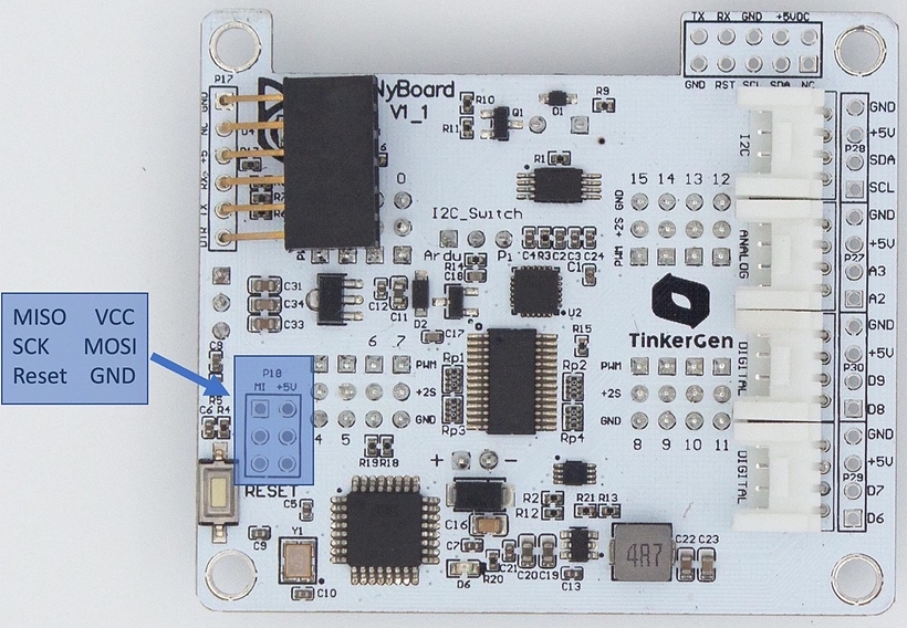
Introduction
The Nyboard V1 used by robot uses the Atmel ATMEGA328P controller, which only supports only one serial port. We separate the serial port of Nyboard to support more modules. The pins of the serial port are compatible with the 6-pin Arduino Pro Mini. Pin definitions are shown in the table below:
Ultrasonic Sensor
Function introduction
Petoi RGB Ultrasonic Sensor is a new module that integrates RGB LED and ultrasonic ranging. Only one GPIO is needed to operate the ultrasonic transceiver. While the ultrasonic probe measures the distance, the other GPIO pin can drive RGB LEDs with various light effects.
14.Play MP3
There is a demo named testMP3 in the "OpenCatEsp32/ModuleTests" file directory. The main function of this demo is to play .mp3 files stored in the SPIFFS file system. Users can choose to play different .mp3 files by inputting 0~6 numbers (.mp3 file index number) in the serial monitor.
Before compiling the demo, please (, development board esp32 2.0.*, library , ).
After compiling, use the latest SPIFFS file upload plugin to upload the .mp3 file to the SPIFFS file system partition of BiBoard. For details, please refer to the chapter .
Useful Tools
Driver
NyBoard Driver to access the USB uploader (adapter)
2
RX
ATMEGA328P RX (receive)
3
TX
ATMEGA328P TX (send)
4
5V
5V power for MCU and chips
5
GND
Ground
6
GND
Ground
The default serial baud rate is 115200bps.
There're 3 communication modules for the NyBoard V1:
Modem signal DTR, reset NyBoard after serial download finished.
//This example code is in the Public Domain (or CC0 licensed, at your option.)
//By Evandro Copercini - 2018
//
//This example creates a bridge between Serial and Classical Bluetooth (SPP)
//and also demonstrate that SerialBT have the same functionalities of a normal Serial
#include "BluetoothSerial.h"
#if !defined(CONFIG_BT_ENABLED) || !defined(CONFIG_BLUEDROID_ENABLED)
#error Bluetooth is not enabled! Please run `make menuconfig` to and enable it
#endif
BluetoothSerial SerialBT;
void setup() {
Serial.begin(115200);
SerialBT.begin("BTSPP_Test"); //Bluetooth device name
Serial.println("The device started,");
Serial.println("Now you can pair it with bluetooth!");
}
void loop() {
if (Serial.available()) {
SerialBT.write(Serial.read());
}
if (SerialBT.available()) {
Serial.write(SerialBT.read());
}
delay(20);
}
// Ain 34 - 0dB Gain - ADC_0db
analogSetPinAttenuation(34, ADC_0db);
// Ain 35 - 2.5dB Gain - ADC_2_5db
analogSetPinAttenuation(35, ADC_2_5db);
// Ain 36 - 6dB Gain - ADC_6db
analogSetPinAttenuation(36, ADC_6db);
// Ain 39 - 11dB Gain - ADC_11db (default)
analogSetPinAttenuation(39, ADC_11db);
"""
In Python 3.8 and earlier, the name of the collection type is
capitalized, and the type is imported from the 'typing' module
"""
# from typing import Union, Optional # for Python 3.9+
from typing import Union, Dict, List, Optional # for Python 3.7
# ip = "192.168.0.108" # for only one robot
ip = ["192.168.0.110", "192.168.0.108"] # for multiple robots
Currently only supports the product Nybble, the software version 2.0, the mode can choose "Ultrasonic" or "RandomMind_Ultrasonic".
You can use the Firmware Uploader within the Petoi Desktop App to finish the configuration.
You can also use Arduino IDE for the most freedom to upload and modify the codes.
Use the latest OpenCat code to finish the setup. As shown below:
If you have already uploaded the latest OpenCat code to make Nybble walk, you only need to uncomment the #define ULTRASONIC at the beginning of OpenCat.ino then upload the code.
If you are not sure, you need to finish the upload process for the standard mode (Step 1 to Step 10) to ensure everything is configured correctly, then upload the code in the Ultrasonic mode.
If the Ultrasonic code is uploaded correctly, you can see success messages printed on the serial monitor of Arduino IDE. As shown below:
Ultrasonic module code realization function: According to the different distances monitored by the ultrasonic module in real-time, the probe inside the ultrasonic module lights up with lights of different colors, and Nybble will make different action responses at the same time.
Arduino IDE 2.0 cannot add the large_spiffs_16MB (4.5MB APP with OTA/6.93MB SPIFFS) configuration option currently.
The SPIFFS file upload plugin in Arduino IDE 1.8.* is written in Java. And Arduino IDE 2.0 is written in a different language (TypeScript + Golang), so the previous upload plugin cannot be used in Arduino IDE 2.0. There is no support for the Arduino IDE 2.0 SPIFFS file upload plugin currently.
So it is recommended that you temporarily install and use the Arduino IDE 1.8.* IDE to upload sketch and .mp3 file.
Of course, you can also use VS Code + PlatformIO to upload the sketch and .mp3 files. For details, please refer to the following documents:
Before uploading the sketch and .mp3 files, please move the "data" folder to the project root directory, store the code files in the "src" directory, and configure the partition option "board_build.partitions" in the platformio.ini in the project root directory, as shown in the following figure:
When you use a USB Type-C interface data cable to upload the firmware for BiBoard or control the robot via the Petoi Desktop App, please download the driver as below:
For example, for Windows:
Mac
You can download the Mac version and run the *dmg file to install. You need to allow the permission settings during the installation.
Win
For Windows, the installation steps are as follows:
In the Device Manager, if you open the Other devices list, you may see a CP210X device with a triangle exclamation sign. Right-click it to find the "update driver" option, then select the unziped folder of your downloaded driver to install.
#include "opencat_serial/opencat_serial.hpp"
int main(int argc, char *argv[])
{
// connect to the serial device
OpenCat::Robot rob("/path/to/port");
// create task
OpenCat::Task task;
// set command type to calibration pose
task.command = OpenCat::Command::CALIB_POSE;
// time delayed after execution
task.delay = 2;
// send command
rob.SendTask({OpenCat::Command::CALIB_POSE, 2});
return 0;
}
The tutorial of using the WiFi module as a MicroPython controller
Part 1: Hardware Setup
1.1 hardware list
USB Uploader (CH340C)
WiFi ESP8266
1.2 Connection
Insert the ESP8266 module into the module configuration interface of the USB uploader, and find the corresponding COM port in the Windows device manager.
Part 2: Software Setup
2.1 Download Thonny
Download the latest version of Thonny, an out-of-the-box Python editor that natively supports MicroPython.
Download address:
2.2 Download the MicroPython firmware
The compiled ESP8266 firmware is provided on the MicroPython official website, because our WiFi module is 4MB, please select the latest firmware with the name of ESP8266 with 2MiB+ flash, and download the bin file.
Firmware download address:
2.3 Upload the MicroPython firmware to the ESP8266 module
There are two ways to upload the MicroPython firmware to the ESP8266 module:
Using the ESPtool download tool, you can more precisely control the partition and use of Flash.
Using Thonny's built-in tool.
For convenience, we use Thonny's built-in tool. The specific steps are as follows:
Open the Thonny, the main interface is as shown below. Thonny uses the Python interpreter in the installation directory by default.
Open Tools -> Options to enter the options page. In the first tab General, we can choose the language we need (needs to be restarted).
8.PWM(Pulse Width Modulation)
1. The introduction of PWM function on BiBoard (ESP32)
The ESP32 used by BiBoard is different from the 328P used by UNO. Because the PWM of ESP32 uses the matrix bus, it can be used on unspecified pins.
The PWM of ESP32 is called LED controller (LEDC). The LED PWM controller is mainly used to control LEDs, and it can also generate PWM signals for the control of other devices. The controller has 8 timers, corresponding to 8 high-speed channels and 8 low-speed channels, totaling 16 channels.
Key Settings of LED PWM Controller's API
Compared with UNO, directly use "analogWrite()" to input any duty ratio between 0-255. The PWM control of ESP32 on BiBoard is more troublesome. The parameters that need to be controlled are as follows:
Manual selection of PWM channels (0-15) also improves the flexibility of the use of pins
The number of bits of the PWM waveform determines the resolution of the duty cycle of the PWM waveform. The higher the number of bits, the higher the accuracy.
The frequency of the PWM waveform determines the speed of the PWM waveform, the higher the frequency, the faster the speed.
The frequency of the PWM waveform and the number of bits are relative, the higher the number of bits, the lower the frequency. The following example is quoted from the ESP32 programming manual:
For example, when the PWM frequency is 5 kHz, the maximum duty cycle resolution can be 13 bits. This means that the duty cycle can be any value between 0 and 100%, with a resolution of ~0.012% (2 ** 13 = 8192 discrete levels of LED brightness).
The LED PWM controller can be used to generate high-frequency signals, enough to clock other devices such as digital camera modules. Here the maximum frequency can be 40 MHz, and the duty cycle resolution is 1 bit. In other words, the duty cycle is fixed at 50% and cannot be adjusted.
The LED PWM controller API can report an error when the set frequency and duty cycle resolution exceed the hardware range of the LED PWM controller. For example, if you try to set the frequency to 20 MHz and the duty cycle resolution to 3 bits, an error will be reported on the serial port monitor.
2. Configure the PWM frequency on BiBoard in Arduinoin Arduino
As shown above, we need to configure the channel, frequency and number of bits, and select the output pin.
Step 1: Configure the PWM controller
Step 2: Configure the PWM output pins
Step 3: Output PWM waveform
In the demo, we choose IO2 as the output pin, connect IO2 to an LED, and you can observe the effect of the LED breathing light.
3. Complete code:
5.EEPROM (Electrically Erasable Programmable read only memory)
The usage of EEPROM is the same as Arduino UNO, there are two operations: read and write.
Read:
I2C address of EEPROM
The internal address of EEPROM (the address for storing data)
Read data
Write:
I2C address of EEPROM
The internal address of EEPROM (the address for storing data)
Write data
In the BiBoard demo, the address of EEPROM on the I2C bus is 0x54, and the capacity is 8192Bytes (64Kbit). We sequentially write a total of 16 values from 0 to 15 in the EEPROM from the first address, and then read them for comparison. Theoretically, the data written in EEPROM and the data read from the corresponding address should be the same.
In the NyBoard factory test, we also use this method, but it is more complicated. We will use a fixed list to fill the EEPROM and read it out for comparison.
Note: the EEPROM operations, especially write operations, are generally not put into the loop() loop. Although the EEPROM is resistant to erasing (100,000 times), if a certain block is frequently written in the loop, It will cause the EEPROM to malfunction.
Introduction
Petoi Desktop App provides a neat graphical user interface to configure the firmware, calibrate the robot, and design customized motions for your robot. The major function modules are the Firmware Uploader, Joint Calibrator, and Skill Composer.
Download & Installation
You can download the latest version of the desktop App and unzip it.
Before running the app, you must use the included USB adapter or the Bluetooth dongle to connect to a Petoi robot.
Windows
Run the UI.exe in the unzipped folder. Do NOT move the UI.exe to another location in Windows.
Mac
After downloading the Mac version, you must drag it into the Application folder.
If you see the error message that "Petoi Desktop App" cannot be opened because the developer cannot be verified, you can right-click the icon, hold the Shift key and click Open.
Linux
Please see the next chapter to run the app from a terminal
Run the app from the Terminal
In the case of compatibility issues, or if you want to modify the source and test, you can also run the code from the Terminal.
The Terminal is a built-in interface on Mac or Linux machines. The equivalent environment on Windows machines is called the Command-Line Tool (CMD). It's recommended that you install to manage your Python environment. It can also provide the Powershell as a Terminal for older Windows machines.
Depending on your existing Python configuration, you may need to upgrade to Python3 and install the following libraries:
pyserial
pillow
You can install them by entering pip3 install pyserial pillow in the Terminal or use the package manager in Anaconda.
To run the code:
In the Terminal, use the cd command to navigate to the OpenCat/pyUI/ folder. You can use the Tab key to auto-complete the path name.
After entering the pyUI/ folder, enter ls and ensure you can see the UI.py and other python source codes listed.
For Linux system users, if you encounter the python error message "_tkinter.TclError: no display name and no $DISPLAY environment variable", you can try to install python3-tk, tk-dev, taking Debian / Ubuntu as an example, the command is as follows:
apt install python3-tk
apt install tk-dev
Open Source Codes
The source code is written with Tkinker in Python3 and is.
UI.py is the general entry for all the modules:
UI.py
-> FirmwareUploader.py
-> Calibrator.py
-> SkillComposer.py
-> translate.py provides multi-language support for the UI. You may help to translate the UI into your language.
ROS
ROS Interface
There's also a ROS wrapper for developpers to easily connect to the ROS environment. It is recommended to use ROS with Raspberry Pi.
Using ROS on Raspberry Pi
Currently, it's recommended to install ROS using docker.
install docker on Raspberry Pi ()
prepare workspace
run the container
source files and build inside the container
run examples (see for more)
Using ROS for remote control
Ros is designed with distributed computing in mind. Here's a simple example on how to run nodes on different machines.
on host machine (usually more powerful than Raspberry Pi)
run service node on Raspberry Pi
send command from host
Examples
using serial library
using ROS service
Remote Controller
It's simple to control Nybble / Bittle via the remote controller.
1. Preparation
The remote doesn't require pairing. Make sure its plastic insulation sheet is removed, and point the remote‘s transmitter to the receiver on the robot's back when operating. If the robot doesn't respond, you can use your phone‘s camera to check the transmitter. If it doesn't blink when clicking a button, you need to change its battery. If it blinks, it may indicate the program on the robot is not configured correctly.
2. Keymap
Only the position of the buttons matters, though those symbols can help you remember the functionalities. It's better to define position-related symbols to refer to those keys, such as K00 for the 1st row and 1st column, and K32 for the 4th row and 3rd column.
Abbreviations for key definitions can reduce SRAM usage. Due to the limited keys of a physical remote, you can change the definitions for convenience.
The following map is just an illustration. Check the #define KXX commandin OpenCat/src/infrared.h for the actual key definitions in effect. They are also open to your customization.
We also made a customized remote panel for future batches. Previous users can download the design file and print it on A4 paper.
3. Check out the following featured motions
Rest puts the robot down and shuts down the servos. It's always safe to click it if Nybble is doing something awkward.
Balance is the neutral standing posture. You can push the robot from the sides and it will try to recover. You can test its balancing ability on a fluctuating board. Balancing is activated in most postures and gaits.
Pressing F/L/R will make the robot move forward/left/right
If the robot keeps beeping after you connect the USB uploader, with numbers printed on the serial monitor, it’s the low voltage alarm being triggered. You need to power the mainboard with the battery to pass the threshold.
The servos are designed to be driven by internal gears. Avoid rotating the servos too fast from the outside.
Joint Calibrator
Robots can be precisely calibrated using the Petoi Desktop App.
** Download the latest version of the . **
BiBoard Extension Hat
Overview
BiBoard Hat V1.0 is the extension board of BiBoard V0 for convenient connection of the voice command and other Grove extensible modules.
13.Add hardware partition configuration option in Arduino IDE
The flash memory of the ESP32 board has 16M, and the range of the storage address expressed in hexadecimal is 0x0-0x01000000.
This is the partition table that has been configured by the system, as shown in the figure below:
The storage location of this partition table file on the computer:
It can be seen from the above partition table: APP0 area and APP1 area are 4.5M each; the data area is SPIFFS, and the size is 6.9M.
PIR Motion Sensor
Function introduction
This sensor allows you to detect the movement of animals, usually the movement of humans within its detection range. Just connect it to the NyBoard and program it, and when anyone moves within its detection range, the sensor will output a high potential on its SIG pin.
Light Sensor
Function introduction
The sensor integrates two photoresistors (depending on the light intensity adjustment resistance) to detect the light intensity. The photoresistor is a special resistance that uses the photoconductive effect, and its resistance is directly related to the intensity of the incident light. When the light intensity increases, the resistance decreases; when the light intensity decreases, the resistance increases. The output signal is an analog value, the brighter the brightness, the larger the value. You can realize the function you want by judging the value of the detected light intensity, such as the function of a robot tracing light.
11.Bluetooth low energy (BLE) serial port pass-through
Bluetooth Low Energy (BLE, Bluetooth Low Energy) serial port pass-through is widely used. On Apple's iOS platform, Classic Bluetooth requires MFi certification to connect with Apple's iOS devices. The Bluetooth low energy device does not have this restriction.
The protocol stack and principle of Bluetooth low energy will not be repeated here, there are many related articles and videos. In short, the bluetooth service is provided in the form of a profile, and there are N characters with independent IDs (UUID) under the profile of each service. Each character has different permissions (read, write, notify, indicate). After the user defines the character and combines it with the authority, a complete service can be provided.
What BLE pass-through is actually to establish a BLE Service, and there are 2 characters under this profile.
One for TX (transmit data) and one for RX (receive data). For this they have different permissions. The following code is to create a new service and character:
Next are two callback functions, which are performed when there is a connection and when there is a write RX character:
Introduction
The head of Bittle is designed to be a clip to hold extensible modules. We compiled a sensor pack with some popular modules, but its contents may change in the future. You can also wire other add-ons thanks to the rich contents of the Arduino and Raspberry Pi communities.
IR Distance Sensor
Function introduction
This module integrates two IR distance sensors, it measures distance through reflected light waves, It is used to detect the presence of an object within a specific range. The sensor consists of an IR LED and a photosensor (phototransistor) pair. The light emitted by the IR LED gets reflected by any object placed in front of the sensor and this reflection is detected by the photosensor(phototransistor). Any white (or lighter) colored surface reflects more than a black (or darker) colored surface. It is suitable to be used to measure complex objects, such as tracing an object.
Gesture Sensor
Function introduction
The sensor features advanced gesture detection, proximity detection and digital ambient light sensing. Gesture detection can accurately sense "up, down, left and right" and more complex movements.
Calibrate puts the robot into calibration posture and turns off the gyro
Stepping lets the robot step at the original spot
Crawl/walk/trot are the gaits that can be switched and combined with the direction buttons
Buttons after trot are preset postures or other skills
Gyro will turn on/off the gyro for self-balancing. Turning off the gyro can accelerate and stabilize the slower gaits. But it’s NOT recommended for faster gaits such as trot. Self-righting will be disabled because the robot no longer knows it's flipped.
Different surfaces have different friction and will affect walking performance. The carpet will be too bushy for the robot's short legs. It can only crawl (command kcr) over this kind of tough terrain.
You can pull the battery pack down and slide along the longer direction of the belly. That will tune the center of mass, which is very important for walking performance.
When the robot is walking, you can let it climb up/down a small slope (<10 degrees)
Don’t keep the robot running for too long. It will overheat the electronics and reduce the servos’ life span.
If you feel something is wrong with the robot, press the reset button on the main board to restart the program.
Be kind as if you were playing with a real kitten/puppy. (^=◕ᴥ◕=^)
# start core
roscore
# start service server
rosrun opencat_server opencat_service_node
# examples using oppencat ros service in C++
rosrun opencat_examples opencat_examples_client_cpp
# examples using opencat ros service in python
rosrun opencat_examples opencat_examples_client_py
class MyServerCallbacks: public BLEServerCallbacks {
void onConnect(BLEServer* pServer) {
deviceConnected = true;
};
void onDisconnect(BLEServer* pServer) {
deviceConnected = false;
}
};
class MyCallbacks: public BLECharacteristicCallbacks {
void onWrite(BLECharacteristic *pCharacteristic) {
std::string rxValue = pCharacteristic->getValue();
if (rxValue.length() > 0) {
Serial.println("*********");
Serial.print("Received Value: ");
for (int i = 0; i < rxValue.length(); i++)
Serial.print(rxValue[i]);
Serial.println();
Serial.println("*********");
}
}
};
if (deviceConnected) {
pTxCharacteristic->setValue(&txValue, 1);
pTxCharacteristic->notify();
txValue++;
delay(10); // bluetooth stack will go into congestion, if too many packets are sent
}
// disconnecting
if (!deviceConnected && oldDeviceConnected) {
delay(500); // give the bluetooth stack the chance to get things ready
pServer->startAdvertising(); // restart advertising
Serial.println("start advertising");
oldDeviceConnected = deviceConnected;
}
// connecting
if (deviceConnected && !oldDeviceConnected) {
// do stuff here on connecting
oldDeviceConnected = deviceConnected;
}
Open the second tab Interpreter, we replace the default Python3 interpreter with MicroPython (ESP8266) and select the corresponding port.
At this time, the ESP8266 module has not yet uploaded the MicroPython firmware. Click "Install or update firmware" in the lower right corner of the above picture to update the firmware using the built-in tool.
Select the port (COMx) where the ESP8266 module is located, and select the location where the downloaded MicroPython firmware (.bin file) is located. Check the flash mode: from image file (keep) (the speed will be slower, but it only needs to be burned once and it is not easy to make mistakes), and check the option Erase flash before installing. Press the Install button.
The progress will be displayed in the lower-left corner of the interface, erase the Flash first, and then write the firmware. When the word Done appears, it means that the programming has been completed.
The software preparation work is over, and the following display will appear after closing the download interface. The red text is garbled because ESP8266 will print a string of codes with a baud rate other than 115200 when it starts up. This code cannot be recognized by MicroPython Shell. When Python’s iconic symbol >>> appears, it means that the firmware is uploaded successfully.
After downloading the compressed file(.zip), please unzip it first.
Do NOT move the UI.exe to another location in Windows.
Prepare for calibration
Make sure you have uploaded the OpenCat Main function firmware before calibrating. Only the software version 2.0 can calibrate the joints via this App.
You need to connect theUSB adapterand USB data cable orBluetooth module(for NyBoard only ) to the computer, install the battery and long-press the button on the battery to power the robot.
Enter the calibration state
After the robot is powered on, there are 2 methods to enter the calibration state:
It will enter the calibration state automatically when you click the Joint Calibrator button.
Click the Calibrate button in the calibrator interface.
The Joint Calibrator interface
Note: Since Nybble uses two more servos (head and tail) than Bittle, the joint index numbers of Nybble and Bittle servos are different, and the calibration poses of Nybble and Bittle after entering the calibration state are also different, as shown in the following picture( The servo slider is not available in the light yellow background area in the interface):
Nybble
Bittle
Install the head
You need to install the battery and long-press the button on the battery to power the robot before installation.
In the calibration state, place the head as close to the central axis as possible and insert its servo shaft into the servo arm of the neck.
Press down on the head so it is firmly attached to the neck.
Install the legs
Install upper leg and lower leg components to the output teeth of the servos after the Bittle is powered on and in the calibrated neutral position. Please keep the torso, upper leg, and lower leg installed vertically as much as possible, and do not install the lower leg backward, as shown in the picture.
The pre-assembled robot should already have the legs properly installed. You can do the joint calibration for fine-tuning.
Use the included L-shaped tool as a reference during calibration. According to the index numbers of the joints shown at the top of the interface (when calibrating the servos, adjust the upper leg first, then adjust the lower leg). Drag the corresponding slider (below the index number), or click the blank part of the slider track to fine-tune the joint to right angles.
Nybble
Bittle
Align the upper leg first
Pay attention to the reference edges for the lower leg
If the offset is more than +/- 9 degrees, you need to remove the corresponding leg and re-install it by rotating one tooth, and then drag the corresponding slider. For example, when it is adjusted to +9 and is still not right, remove the corresponding leg and shift one tooth when attaching it. Then you should get a smaller offset in the opposite direction.
You can switch between "Rest", "Stand up"and "Walk" to test the calibration effect.
If you want to continue calibrating, please click the Calibration button, and the robot will be in the calibration state again (all servos will move to the calibration position immediately).
Note:
You may need a second round of calibrations to achieve optimal results.
After calibration, remember to click the "Save" button to save the calibration offset. Otherwise, click the "Abort" button to abandon the calibration data. You can save the calibration in the middle in case your connection is interrupted.
When you close this window, there is a message box shown below:
If you want to save the calibration data, please click the "Yes" button; otherwise, click the "No" button. Click the "Cancel" button to cancel to quit.
Install the screws
After completing the joint calibration, install the center screws to fix the leg parts and servo gears.
The extension hat has an onboard voice command module and four grove sockets.
1x Serial2 port (GPIO16, 17).You must dial the slide switch to UART2 to free it for regular serial communication or GPIO. In that case, the Tx pin (GPIO 17) can be used to write.
1x I2C port (GPIO21, 22). It's already used by the main program to read sensors. If you use the BiBoard as a regular ESP32 board without Bittle's firmware, they can be configured as regular GPIO pins to read and write.
2x input-only pins (GPIO 34, 35, 36, 39).
No.
Module
Introducion
1
A built-in module on the BiBoard
2
UART2/Voice command switch
Connect grove port to UART2 or the Voice command module
Introduction to the onboard components
Voice command module
It's equivalent to the independent Grove voice module introduced in the extensible modules.
Grove sockets
We adopted the Grove sockets for convenient plug-and-play connections. There are three types of sockets:
Grove Socket
Pin Number
Function
G1
I2C: SDA (GPIO21), SCL (GPIO22)
I2C with 3.3V logic signal
G2
TX (GPIO17), RX (GPIO16)
BiBoard provides the 5V power supply of the grove sockets, while the 5V comes from the battery. So the devices connected to the Grove sockets can only work when connected to the BiBoard and powered by the battery.
BiBoard's 3.3V powers the voice module. The 3.3V can be supplied from the USB. So it can work without battery power.
UART2 / Voice command switch
UART2 shares the GPIO ports with the voice command module. When the switch is dialed to VOICE COMMAND, the Serial2 port can NOT be used. You can dial the slide switch to UART2 to free it for regular serial communication or GPIO.
The function of the switch is shown in the figure below:
But in the Arduino IDE, this configuration is not included in the hardware partition configuration options of the ESP32 Dev Module:
We need to add this configuration to the ESP32 Dev Module.
Locate the name of the development board: esp32.name=ESP32 Dev Module, as shown in the figure below:
The line of text in the ESP32 Dev Module partition configuration in the configuration file:
Add the following 3 lines of text below this line:
The following explains the meaning of the three lines of text:
The name of the ESP32 partition configuration, we named it BiBoard V0 (4.5M APP with OTA /6.9 MB SPIFFS), or it can be replaced with other names you are familiar with.
The partition configuration file information is the file large_spiffs_16MB.csv . You can also write a partition file to adjust the file size of the APP and data area.
This line of text specifies that the maximum upload program size is 4685824 bytes.
Let's try to compile a simple program to test whether the above configuration is set successfully.
Reopen the Arduino IDE, we can see the BiBoard just configured:
After compiling the program, the result is as shown in the figure below:
Compilation is complete, using 213KB of Flash (4%), and the maximum usable size is 4,685,824 bytes.
In this passage, “4685824 bytes” is specified in the third line of text just added to the configuration file.
If you use Arduino IDE 2.0.*, the partition option may not appear automatically. To fix:
Select File > Quit from the Arduino IDE menu to close all active Arduino windows and quit the process.
Delete the "User data" folder:
Windows:
Linux:
Restart the Arduino IDE.
The custom board options menus should now reflect any changes that were made to boards.txt.
So far, you have completed the configuration of the development board with the largest flash memory space in Arduino IDE.
Hardware setup
NyBoard
Connecting to the NyBoard with wire as shown in the following picture:
BiBoard
For specific use, the end connected to the sensor can be fixed on the robot's head (included in Bittle's mouth or attached to the top of Nybble's head), of course, you can also use your creativity according to your needs.
Software setup
The code using this sensor has been integrated into the OpenCat (NyBoard)/ OpenCatEsp32 (BiBoard) project. Uncomment the line #define PIR in the OpenCat.ino / OpenCatEsp32.ino, as shown in the figure below, and then use the Arduino IDE to upload the sketch to the robot main board, which can reproduce the example function of integrating the robot action.
NyBoard
Prepare the Arduino UNO development environment
With NyBoard V1_*, you can simply choose Arduino Uno.
If you want to test the function of a PIR motion sensor alone or want to learn more about its principles. You can use the Arduino IDE to upload the demo sketch(test_Touch_Reflection_PIR.ino), as shown below:
This demo sketch implements real-time printing of sensor detection results in the serial monitor - when anyone moves within its detection range, print 1; otherwise, print 0.
The demo code
The demo code is in the OpenCat code repository on GitHub (specific path: OpenCat/ModuleTests/test_Touch_Reflection_PIR). You can visit our GitHub code repository https://github.com/PetoiCamp/OpenCat to download the complete code, as shown in the following picture:
Hardware setup
NyBoard
Connecting to the NyBoard with wire as shown in the following picture:
BiBoard
For specific use, the end connected to the sensor can be fixed on the robot's head (included in Bittle's mouth, or attached to the top of Nybble's head), of course, you can also use your creativity according to your needs.
Software setup
The code using this sensor has been integrated into the OpenCat (NyBoard)/ OpenCatEsp32 (BiBoard) project. Uncomment the line #define DOUBLE_LIGHT in the OpenCat.ino / OpenCatEsp32.ino, as shown in the figure below, and then use the Arduino IDE to upload the sketch to the robot main board, which can reproduce the example function of integrating the robot action.
NyBoard
Prepare the Arduino UNO development environment
With NyBoard V1_*, you can simply choose Arduino Uno.
If you want to test a light sensor's function alone or learn more about its principles. You can use the Arduino IDE to upload the demo sketch(doubleLight.ino), as shown below:
This demo sketch implements real-time printing of the analog values of the two analog pins (A2 and A3) in the serial monitor. You can also use the serial plotter to view the two analog pins (A2 and A3) more intuitively. The waveform graph is generated by the analog value of the pin output along the time axis.
The touch, reflection, and PIR sensors can generate digital 1 or 0 as a switch signal. So, they should be connected to the digital Grove socket. We use the fourth socket with D6 and D7 in the demo code.
Connecting to the NyBoard with wire as shown in the following picture:
BiBoard
For specific use, the end connected to the sensor can be fixed on the robot's head (included in Bittle's mouth, or attached to the top of Nybble's head), of course, you can also use your creativity according to your needs.
Software setup
Install the latest version of the Adafruit NeoPixel library using the Arduino IDE.
The code using this sensor has been integrated into the OpenCat (NyBoard)/ OpenCatEsp32 (BiBoard) project. Uncomment the line #define DOUBLE_INFRARED_DISTANCE in the OpenCat.ino / OpenCatEsp32.ino, as shown in the figure below, and then use the Arduino IDE to upload the sketch to the robot main board. The sketch can reproduce the example function of integrating the robot action.
NyBoard
Prepare the Arduino UNO development environment
With NyBoard V1_*, you can simply choose Arduino Uno.
If you want to test the function of this sensor alone or want to learn more about its principles. You can use the Arduino IDE to upload the demo sketch(testDoubleInfraredDistance.ino), as shown below:
This demo sketch implements real-time printing of the analog values (rL, rR) and data that have been processed (dL,dR) of the two analog pins (A2 and A3) in the serial monitor. You can also use the serial plotter to view the two analog pins (A2 and A3) more intuitively. The waveform graph is generated by the analog value of the pin output along the time axis.
The demo code
The demo code is in the OpenCat code repository on GitHub (specific path: OpenCat/ModuleTests/testDoubleInfraredDistance). You can visit our GitHub code repository https://github.com/PetoiCamp/OpenCat to download the complete code, as shown in the following picture:
Software setup
Install the latest version of the Arduino_APDS9960 library using the Arduino IDE.
The code using this sensor has been integrated into the OpenCat (NyBoard)/ OpenCatEsp32 (BiBoard) project. Uncomment the line #define GESTURE in the OpenCat.ino / OpenCatEsp32.ino, as shown in the figure below, and then use the Arduino IDE to upload the sketch to the robot main board, which can reproduce the example function of integrating the robot action.
NyBoard
Prepare the Arduino UNO development environment
With NyBoard V1_*, you can simply choose Arduino Uno.
If you want to test the function of a gesture sensor alone or want to learn more about its principles. You can use the Arduino IDE to upload the demo sketch(gesture.ino), as shown below:
Hardware setup
NyBoard
After uploading the sketch, connect to the NyBoard with wire, as shown in the following picture:
BiBoard
For specific use, the end connected to the sensor can be fixed on the robot's head (included in Bittle's mouth or attached to the top of Nybble's head); of course, you can also use your creativity according to your needs.
This demo sketch (gesture.ino) implements real-time printing of various directional gestures (up, down, left, and right) made by the user in front of the gesture sensor in the serial monitor.
You need to unplug the 6-pin USB adpter for the NyBoard before mounting the Pi to the board.
You can solder a 2x5 socket on NyBoard to plug in a Raspberry Pi. Pi 3A+ is the best fit for NyBoard's dimension.
Nybble
Bittle
After you solder on the socket, you won't be able to install the back cover of Bittle.
The red can be 3D printed.
As shown in the , the arguments of tokens supported by Arduino IDE's serial monitor are all encoded as Ascii char strings for human readability. While a master computer (e.g. RasPi) supports extra commands, mostly encoded as binary strings for efficient encoding. For example, when encoding angle 65 degrees:
Ascii: takes 2 bytes to store Ascii characters '6' and '5'
Binary: takes 1 byte to store value 65, corresponding to Ascii character 'A'
What about value -113? It takes four bytes as an Ascii string but still takes only one byte in binary encoding, though the content will no longer be printable as a character.
Obviously, binary encoding is much more efficient than the Ascii string. However, the message transferred will not be directly human-readable. In the OpenCat repository, I have put a simple Python script that can handle the serial communication between NyBoard and Pi.
1. Config Raspberry Pi serial port
In Pi's terminal, type sudo raspi-config
Under the Interface option, find Serial. Disabled the serial login shell and enable the serial interface to use the primary UART:
Run raspi-config with sudo privilege: sudo raspi-config.
Find Interface Options -> Serial Port.
At the option Would you like a login shell to be accessible over serial?
You also need to DISABLE the to avoid repeating reset signals sent by Pi's GPIO 4.
If you plug Pi into NyBoard's 2x5 socket, their serial ports should be automatically connected at 3.3V. Otherwise, pay attention to the Rx and Tx pins on your own AI chip and its voltage rating. The Rx on your chip should connect to the Tx of NyBoard, and Tx should connect to Rx.
Note: If you installed UbuntuOS on Raspberry Pi, please config it as follows:
add enable_uart=1 to /boot/config.txt
If you are using generic Linux system, once the uploader is connected to your computer, you will see a “ttyUSB#” in the serial port list. But you may still get a serial port error when uploading. You will need to give the serial port permission. Please go to this link and follow the instructions:
2. Change the permission of
If you want to run it as a bash command, you need to make it executable:
chmod +x ardSerial.py
You may need to change the proper path of your Python binary on the first line:
#!/user/bin/python
3. Use ardSerial.py as the commander of robot
NyBoard has only one serial port. You need to UNPLUG the USB adapter if you want to control Bittle with Pi's serial port.
Typing ./ardSerial.py <args> is almost equivalent to typing <args> in Arduino's serial monitor. For example, ./ardSerial.py kcrF means "perform skill crawl Forward".
Both ardSerial.py and the parsing section in OpenCat.ino need more implementations to support all the serial commands in the protocol.
For Nybble:
Reduced motion capability may happen when connected to Pi! A stronger battery is needed.
Python coding mode in Mind+
If you are familiar with the Petoi coding blocks and Python language, you can change to the Code mode in Mind+ as follows:
The Code mode is a Python3 development environment. You can write any Python script in it and call all the API interfaces of the PetoiRobot library imported by Mind+.
You can find the PetoiRobot library in the following directory, there are all the definitions of API interfaces in the PetoiRobot.py
Windows
C:\Users\{username}\AppData\Local\DFScratch\extensions\petoi-robot-thirdex\python\libraries\PetoiRobot.py
Below are the supported functions in the library. You may refer to the auto-generated Python code in the Blocks mode to learn its formats.
Here is a sample code :
You can also copy the code in the Auto Generate area in the Blocks mode and then paste it into the code file in the Code mode. Then you can edit and run the code.
15.The usage of Wi-Fi OTA(Over-The-Air)
The Arduino demo of ESP32 provides the function of OTA (updating/uploading a new program to ESP32 using Wi-Fi)
1. What is OTA?
The configuration of our BiBoard is 16MB Flash, and the specific partitions are as follows:
OTA mainly operates OTA data areas, namely APP1 and APP2 areas. The principle is:
BiBoard runs the firmware with OTA function, at this time, the boot points to the APP1 area.
The OTA command is sent to ESP32 via Wi-Fi, and the binary file of the upgrade program is transferred to the APP2 area.
If the transmission of APP2 is completed and the verification is successful, OTAdata points to the APP2 area, and the next time it starts from the updated firmware area (APP2), the APP1 data is retained. Next time, OTA will write to APP1 area to overwrite the old firmware.
If the transmission of APP2 is not completed due to a network transmission error, because APP2 has not passed the verification, OTAdata does not point to the APP2 area. The program in the APP1 area will still be executed after the reset is started, and the damaged APP2 area will be completely erased and overwritten during the next OTA.
OTA operation in Arduino program
In the demo, first configure WiFi, and configure the WiFi mode as STA (Station, base station mode). Enable the WiFi function and pass in the account password "WiFi.begin(ssid, password);"
When the Wi-Fi is successfully connected, the IP address will be printed via the serial port; if the connection is wrong, the ESP32 will restart.
In the demo, you can configure the port number, the OTA key or the hash of the key, and the area and type of the OTA (commented by default).
The following are several code snippets similar to callback functions, which are used to judge the state of each stage of OTA.
After configuring according to the demo, call "ArduinoOTA.handle();" in the loop function. The following analogWrite function is to distinguish the effects of different firmware updates (by changing the value).
The first time you use the serial port to download, the python tool "esptool" is called. You can use OTA after the download is complete. In the port options, you will find an extra port based on the IP address, which is the OTA address.
Select this address, the lower right corner is the IP address of ESP32 Dev Module on your BiBoard (192.168.1.178)
At the same time, a warning will pop up: "Serial monitor is not supported on network ports such as 192.168.1.178 for the ESP32 Dev Module in this release".
The ESP32 OTA of Arduino is only suitable for updating the program and cannot complete the serial port debugging work. If you need to debug BiBoard, please connect the USB-C interface.
Download the program, as shown in the figure.
Touch Sensor
Function introduction
The sensor contains two touch parts (left and right) and can detect changes in capacitance when a finger approaches. This means the touch sensor will output a high level whether your finger touches lightly or presses hard. You can realize the function you want by judging the detected value (1 for high level, 0 for low level).
Hardware setup
NyBoard
Connecting to the NyBoard with wire as shown in the following picture, connect to the NyBoard Grove interface which include D6, D7:
BiBoard
For specific use, the end connected to the sensor can be fixed on the robot's head (included in Bittle's mouth, or attached to the top of Nybble's head), of course, you can also use your creativity according to your needs.
Software setup
The code using this sensor has been integrated into the (NyBoard)/ (BiBoard) project. Uncomment the line #define DOUBLE_TOUCH in the OpenCat.ino / OpenCatEsp32.ino, as shown in the figure below, and then use the to upload the sketch to the robot main board, which can reproduce the example function of integrating the robot action.
NyBoard
Prepare the Arduino UNO development environment
With NyBoard V1_*, you can simply choose Arduino Uno.
BiBoard
Arduino C++ demo
If you want to test the function of a touch sensor alone or want to learn more about its principles. You can use the Arduino IDE to upload the demo sketch(doubleTouch.ino), as shown below:
This demo sketch implements real-time printing of the detection values of D6 and D7 pins in the :
The demo sketch
Mind+ Demo
If you want to use the sensor with the Mind+ program for NyBoard:
You can upload the firmware via the Petoi Desktop App:
Or you can upload the OpenCat.ino as follows, uncomment the line #define GROVE_SERIAL_PASS_THROUGH in the OpenCat.ino:
For BiBoard, you can skip this step.
2. Follow to import the Petoi Coding Blocks in the app Mind+, and load the Mind+ code file.
Connect the robot and computer with the (USB uploader) or .
Power on the robot and click the Run button in Mind+.
Mind+ demo code
Setup WebREPL
Realize remote debugging and upload script
The previous tutorial realized the function of the robot to perform sequence actions by editing Python code offline. But this is very inconvenient. Whenever we need to modify the code, we need to unplug the WiFi module for modification, and we cannot flexibly pause and modify parameters during execution. The reason is that ESP8266 only has one serial port, and we need to use it to communicate with NyBoard. Fortunately, MicroPython uses the WiFi function provided by ESP to realize remote wireless Python debugging - WebREPL.
On the basis of official documents, combined with the characteristics of ESP8266, we wrote the following tutorials:
1. Enable webREPL
After connecting the device, enter import webrepl_setup in the shell interface, and input according to the prompt information:
Enable it running on boot: E
Set password for it: your own password(e.g. 1234)
Repeat the password to confirm
2. The script to setup webREPL
We use the demo script below, to replace the SSID and password with the network information your own around you.
After running the script, it will keep trying to connect to the WiFi network. Once connected, it will automatically start the WebREPL service of the device.
Remember this IP address (automatically assigned by router DHCP), useful when configuring WebREPL.
3. Configure the WebREPL service
We are now debugging the Python script through WebREPL, and the previous serial port is used to communicate with NyBoard. So in the options, change the previous USB-COMx interface to WebREPL.
Then we fill in the IP address, port and password of WebREPL, and click OK.
When WebREPL Connected is displayed, the connection is successful.
We can try some simple scripts, such asblink.py.
WebREPL saves serial ports and supports wireless debugging. The disadvantage is that the speed is slow (because of network delay), and the waiting time for software reset is relatively long.
4. Separate the serial port from the debugger
Now we can use webREPL to debug the script, but when we open the serial port monitor, we will find that whenever we run the script, the serial port will send out a series of debugging content: These massive strings will cause the NyBoard to be too late to process and crash. As shown below:
We hope that when debugging the program, the serial port only outputs the commands we want to output, not the Debug information. Open the boot.py on the device, uncomment the line of code uos.dupterm(None, 1) and save it , and unbind the serial port and REPL debug. Restart the module, and the serial port debugging assistant will no longer print the debug information.
As a supplement, we can output debug information through the print() statement, which will be displayed in the Shell through WiFi.
So far, you can easily use the ESP8266 to debug robot through webREPL to edit action sequences based on MicroPython.
USB Uploader (CH340C or CH343G)
The module uses a CH340C USB bridge. Windows10, Linux, and macOS are all drive-free. The specific interface is shown in the following figure:
NyBoard download interface: used to connect to NyBoard, download program firmware to the robot, and communicate with the computer via serial port.
Communication module debugging interface: used to connect the Bluetooth or WiFi module, update the module program and debug the parameters. In order to avoid the cumbersome operation when connecting with Dupont wires, the pin ordering is slightly different from the NyBoard download interface - the TX/RX interface is reversed, and a GND pin becomes an RTS pin. For details on how to use the debugging interface of the communication module, see the following chapters.
Do not plug in the NyBoard and the other module(WiFi or Bluetooth) at the same time! That will block the serial port.
Connect NyBoard
Insert the 6-pin(H1) of the USB uploader to the NyBoard's uploader socket and then use the included USB data cable to insert one end into the MicroUSB interface of the USB upload module; the other end into the USB interface of the PC.
Right-click on "This PC" on the Windows desktop, and then click on "Manage" with the left mouse button (of course, you can also operate in the folder browser), as shown in the figure below, and then select "Device Manager" in the "Computer Management" page to check the connected serial port:
Open the Arduino IDE, or the Desktop App Firmware Uploader interface, and select the corresponding COM port to upload the firmware for the NyBoard and use the serial monitor to communicate.
The uploader has three LEDs: power, Tx, and Rx. Right after the connection, the Tx and Rx should blink for one second indicating initial communication, then dim. Only the power indicator LED should keep lighting up. You can find a new port under Tool->Port as
“/dev/cu.usbserial-xxxxxxxx” (Mac)
“COM#” (Windows)
“ttyUSB#” (Linux)
For Linux, once the uploader is connected to your computer, you will see a “ttyUSB#” in the serial port list. But you may still get a serial port error when uploading. You will need to give the serial port permission. Please go to this link and follow the instructions:
If Tx and Rx keep lighting up, there’s something wrong with the USB communication. You won’t see the new port. It’s usually caused by overcurrent protection by your computer, if you’re not connecting NyBoard with an external power supply and the servos move all at once.
The Drivers
CH340
If you cannot find the serial port after connecting to your computer, you may need to install the driver for the CH340 chip.
Mac:
Windows:
Linux:
CH343G (with two USB ports)
The CH343G version should install the driver automatically on most systems. However, if you are using the module on Mac to configure the ESP8266 module, please download the driver. It will be recognized as two USB devices (usbserial and usbmodem). You may try either one to connect.
For ChromeOS:
Download the Arduino IDE(e.g. 1.8.19) for Linux from
Install it on the Chromebook. Please refer to the video at
OpenCat Imitation Tutorial
Let the robot be your Avatar!
In this tutorial, we will introduce how to use the Ailia in python language to implement an OpenCat robot to imitate various human body movements.
To clone or download the code from the GitHub repository, you can clone the code with the following command:
1. Run on a regular computer (Mac/Linux)
Requirements
Python 3.6 and later
It is recommended to install the IDE. For the specific installation method, please refer to the following link:
Open the Anaconda Prompt (Windows) or the Terminal (Linux / macOS) and enter the following commands to create and activate a virtual environment (the environment name is "venv", and can also be customized to other names):
conda create --name venv
conda activate venv
You can execute run.sh within OpenCat-Imitation/ with your shell command directly. It wraps up the above commands.
2. Run on the Jetson Nano 2GB Developer kit
You may want to run the demo on a Jetson Nano to experiment with some GPU features.
The developer kit uses a microSD card as a boot device and for main storage. It’s important to have a card that’s fast and large enough for your projects; the minimum requirement is a 32GB UHS-1 card. Many projects with Jetson Nano 2GB Developer Kit will utilize swap space on the MicroSD Card due to only 2GB physical memory. For this reason, we recommend 64GB or larger microSD cards. High-endurance microSD cards are also recommended.
Please refer to to record the system image file () into the microSD card and complete the system initialization.
The system image file link in the user guide () points to JetPack 4.6.1, download and burn it to a microSD card After that, system initialization may fail when the Jetson Nano is started. So we recommend using the earlier version: JetPack 4.6.
2. Use a network cable to connect the Jetson Nano development board to a router or other computer hosts so that it can access the Internet.
3. Clone or download the code from , and install the Ailia SDK according to , the specific method is the same as the above step 3 in Run on the host computer, but NO need to execute the statement:
pip install -r requirements.txt
4. Install the relevant python library files using the following command:
5. Connect the camera and complete its configuration by referring to .
Please refer to the technical documentation to complete the setup if you use a USB camera to complete the setup.
To connect the USB uploader, you need to use the following command:
sudo usermod -a -G dialout $USER to increase user rights.
6. Start the program, please refer to step 4 and 5 of .
Now the OpenCat imitation program can run on the Jetson Nano development board. You can refer to other relevant technical documents to improve the program's performance, such as .
Battery
The robot battery
Though you can program BiBoard directly or NyBoard with the USB uploader, external power is required to drive the servos separately.
When the mainboard is powered by USB, the blue LED lights up. When external batteries power the mainboard, the yellow LED lights up.
Parameters
Rechargeable Li-ion Battery
Model: ZCF503060
Rated Capacity: 1000mAh/7.4Wh
Input: 5V-1.5A
The servos require 7.4~8.4V external power to move. Our customized Li-ion battery has a built-in charging and protection circuit. Clicking the battery's button will show its status. Blue light indicates it has power, and red means the power is low. Long-pressing the button for 3 seconds to power on/off the battery.
Connection and Power On
Be careful with the polarity when connecting the power supply. The terminal on the main board has an anti-reverse socket, so you won't be able to plug in the wrong direction. See for the detailed connection instructions. Before powering, insert the battery's plug into the main board's terminal.
Reversed connection may damage your NyBoard!
Battery Life
It can last hours if you're mainly coding and testing postures or less than 30 minutes if you keep Bittle running.
Use senario
Battery life
The battery light will turn red when the power is low and will soon be cut off automatically.
Charging
Use a 5V-1A USB charger to charge the battery. We don't recommend using fast chargers. The battery will NOT supply power during charging. Keep the battery in your sight when charging.
During the charging process, the red LED light is on.
When the charging is finished, the green LED light is on.
WARNING:
The battery should be charged under adult supervision, for battery charged using a battery charger for use by children, the battery is only to be charged by persons of at least eight years old.
The supply terminals are not to be short-circuited.
After Using
After using, remember to turn off the battery. The blue LED will stay light if the USB power still powers it. You can check if the yellow LED on the main board is turned off.
Attaching the Battery to the body
The battery can be attached to the robot's body conveniently without any screws. Check the following video:
The infrared remote control's battery
The infrared remote control's battery is a coin battery. Its model is CR2025.
Please remove the plastic insulator when opening the package for the first time and using the remote control.
To remove and install the battery, please follow the diagram on the back of the remote control.
This coin battery is not to be recharged;
The battery is to be inserted with the correct polarity (+ and -);
Exhausted battery is to be removed from the remote control;
WARNING: Contains coin battery. Hazardous if swallowed - see instructions.
WARNING: This product contains a coin battery. If swallowed, the battery can cause serious internal chemical burns.
WARNING: Dispose of used batteries immediately. Keep new and used batteries away from children. If you think batteries might have been swallowed or placed inside any part of the body, seek immediate medical attention.
WARNING:
This product contains a Coin Cell Battery. A swallowed Coin Cell Battery can cause internal chemical burns in as little as two hours and lead to death. Dispose of used batteries immediately. Keep new and used batteries away from children. If you think batteries might have been swallowed or placed inside any part of the body, seek immediate medical attention.
MU Camera
Function introduction
Petoi Intelligent Vision Sensor can recognize many objects with a deep-learning algorithm. For example, it can detect color blocks, balls, the human body, and cards. Its detection result can be transmitted through the UART or I2C interface. MU is compact, has low power consumption, processes all algorithms locally, and can be widely used in intelligent toys, AI+STEAM lessons, creators, and other products or fields.
Software setup
You can use the Firmware Uploader within the Petoi Desktop App.
Currently, the only supports Bittle, NyBoard, and software version 2.0; please select Camera as the mode for the board versions NyBoard_V1_x.
You can also use for the most freedom to upload and modify the codes.
First, download and install the into your Arduino IDE.
2. Use the latest / code to finish the setup.
NyBoard using OpenCat.ino
If you have already uploaded the latest OpenCat code to make Bittle / Bittle X walk, you only need to uncomment #define CAMERA at the beginning of OpenCat.ino, then upload the code.
If unsure, you need to finish the (Step 1 to Step 10) to ensure everything is configured correctly, then upload the code in the camera mode.
BiBoard using OpenCatEsp32.ino
Set the for BiBoard and modify the source code as follows:
Hardware setup
After uploading the firmware, switch the dial switches on the MU Vision Sensor and connect to the mainboard with wire as shown in the following picture:
NyBoard
BiBoard
Note: The position of the left and right switches (left: down and up; right: down and down) must be dialed to the position shown in the figure.
Fix the end connected to the camera to the robot's head (included in Bittle's / Bittle X's mouth).
If the camera code is uploaded correctly, Bittle / Bittle X maintains the rest position. Success messages are printed on the of Arduino IDE. When the MU Vision Sensor recognizes a target, the two LEDs will turn blue, and Bittle's / Bittle X's head can follow the target and swing left and right. The demo code will auto-switch the target between a yellow tennis ball and a human body if it fails to find any object.
FAQ
If the MU Vision Sensor cannot identify the target object, please press the reset button on the camera, then press the reset button on the main board.
While the MU Vision Sensor connects with BiBoard if the white LED on the back of the MU Vision Sensor isn't lit up.
Please plug in the battery to the BiBoard and long-press the button on the battery to power the BiBoard. Then, click the camera's reset button and the main board's reset button in order.
In the control panel, you can control the robot to perform various postures, behaviors, and gaits.
Gaits
The left panel sets both the robot's gaits and directions and send combined command, such as "walk left" and "trot forward". The robot will only move if an initial gait and direction are selected. The "step" has no direction, and "backward" has left and right directions. The pause button "||" will pause the robot's motion and turn off the servos, so that you can rotate the joints to any angle. The "Turbo" button ( ) turns on/off the gyro, a sensor to detect the robot's body orientation. Turning it on will make the robot keep adjusting to body angles, and will know when it's upside down. Turning it off will reduce calculation and make it walk faster and more stable.
Run MicroPython on ESP8266
After uploading the MicroPython firmware on ESP8266, we can use it run MicroPython scripts.
1. Run the script directly
We can execute the python scripts directly in the interpreter.
Dual Mode Bluetooth
Introduction
The Bluetooth module is a standard transparent transmission module, which sends serial port data to devices connected to Bluetooth.
You can wirelessly upload firmware or control the motion of the robot through a Bluetooth connection. You can even control the robot using our smartphone app . We have included our official Bluetooth module in the standard robot kit. As shown below:
12.File system SPIFFS
ESP32 File System SPIFFS Configuration Guide
1. Why use a file system
On BiBoard (ESP32), in addition to the regular program area and boot area, we use the file system in the Flash partition.
The role of a file system with independent partitions is as follows:
const int freq = 5000; // PWM frequency
const int ledcChannel = 0; // ledc channel, 0-15
const int resolution = 8; // resolution of PWM,8bit(0~255)
ledcSetup(ledcChannel, freq, resolution);
ledcAttachPin(ledPin, ledcChannel);
ledcWrite(ledcChannel, dutyCycle);
/* In this demo, we show how to use PWM in BiBoard(ESP32)
* It's different from the Arduino UNO based on the ATMega328P
*/
// define the PWM pin
const int ledPin = 2; // 16 corresponds to GPIO16
// setting PWM properties
const int freq = 5000; // PWM frequency
const int ledcChannel = 0; // ledc channel, in ESP32 there're 16 ledc(PWM) channels
const int resolution = 8; // resolution of PWM
void setup(){
// configure ledc functionalitites
// channels 0-15, resolution 1-16 bits, freq limits depend on resolution
// ledcSetup(uint8_t channel, uint32_t freq, uint8_t resolution_bits);
ledcSetup(ledcChannel, freq, resolution);
// attach the channel to the GPIO to be controlled
ledcAttachPin(ledPin, ledcChannel);
}
void loop(){
// increase the LED brightness
for(int dutyCycle = 0; dutyCycle <= 255; dutyCycle++){
// changing the LED brightness with PWM
ledcWrite(ledcChannel, dutyCycle);
delay(15);
}
// decrease the LED brightness
for(int dutyCycle = 255; dutyCycle >= 0; dutyCycle--){
// changing the LED brightness with PWM
ledcWrite(ledcChannel, dutyCycle);
delay(15);
}
}
# use to print debug information
def printH(head, value)
# deactivate the Gyro
def deacGyro()
# get the current angle list of all joints
def getAngleList()
return angleList
# get the current angle value of a joint
def getCurAng(index)
# creat an absolut value list
def absValList(num1, num2)
# rotate angle from relative value to absolute value
# creat an offset value list
def relativeValList(index, symbol, angle)
# rotate the joints sequentially or simultaneously
def rotateJoints(token, var, delayTime)
# play tones
def play(token, var, delayTime)
# encode the character to bytes
def encode(in_str, encoding='utf-8')
def printSkillFileName()
# open the serial port
def openPort(port)
# auto connect serial ports
def autoConnect()
# send a short skill string
def sendSkillStr(skillStr, delayTime)
def loadSkill(fileName, delayTime):
# send a command string
def sendCmdStr(cmdStr, delayTime)
def sendLongCmd(token, var, delayTime)
# get the analog value of a pin
def readAnalogValue(pin)
# get the digital value of a pin
def readDigitalValue(pin)
# set the analog value of a pin
def writeAnalogValue(pin, val)
# set the digital value of a pin
def writeDigitalValue(pin, val)
# close the serial port
def closePort()
# The code starts here
from PetoiRobot import * # must import the PetoiRobot library
# enter the code below
# auto connect serial ports
autoConnect()
# call the APIs to control the Petoi robot
sendSkillStr('ksit', 0.5)
sendCmdStr('T', 0.5)
loadSkill("skillFileName", 0.2)
# close the serial port
closePort()
import network
import time
import webrepl
def do_connect():
# WiFi SSID and Password
wifi_ssid = "YOUR SSID" # YOUR WiFi SSID
wifi_password = "YOUR PASSWORD" # YOUR WiFi PASSWORD
# Wireless config : Station mode
station = network.WLAN(network.STA_IF)
station.active(True)
# Continually try to connect to WiFi access point
while not station.isconnected():
# Try to connect to WiFi access point
print("Connecting...")
station.connect(wifi_ssid, wifi_password)
time.sleep(10)
# Display connection details
print("Connected!")
print("My IP Address:", station.ifconfig()[0])
if __name__ == "__main__":
do_connect()
webrepl.start()
Connected!
My IP Address: 192.168.xxx.xxx
WebREPL daemon started on ws://192.168.xxx.xxx:8266
Started webrepl in normal mode
macOS:
select 'No'.
At the option Would you like the serial port hardware to be enabled? select 'Yes'.
Exit raspi-config and reboot for changes to take effect.
remove console=serial0,115200 from /boot/firmware/cmdline.txt on Ubuntu and similar to/boot/cmdline.txt on Raspberry Pi OS
make sure you have pyserial installed if you're using the python serial library, not python-serial from apt.
create the following udev file (I created /etc/udev/rules.d/50-tty.rules):
reload your udev rules: sudo udevadm control --reload-rules && sudo udevadm trigger
change the group of the new serial devices:
The devices are now under the tty group. Need to add the user to the tty group and dialout group:
update the permissions for group read on the devices:
reboot
Or just create a script that will do this automatically.
With the additional current drawn by Pi, Nybble will be less capable for intense movements, such as trot (the token isktr). The system is currently powered by two 14500 batteries in series. You may come up with better powering solutions, such as using high drain 7.4 Lipo batteries, or 2S-18650. There are a bunch of considerations to collaborate software and hardware for balanced performance. With Nybble's tiny body, it's better to serve as a platform for initiating the communication framework and behavior tree rather than a racing beast.
Follow the guide to install the Ailia SDK, it will be used for pose detection. The guide mainly includes the following steps: download and install the ailia SDK and the related python library files.
When downloading the Ailia SDK, you need to enter the correct email address to receive the download link address and license file. The free license is valid for only one month. The SDK is about 2GB, so it takes time to download.
Move the downloaded license file (AILIA.lic) to the directory where bootstrap.py is located ({ailia sdk directory}/python), and then follow the steps to continue installing the Ailia SDK.
cd {ailia sdk directory}/python
python3 bootstrap.py
pip3 install .
Download the requirements.txt from this page (https://github.com/axinc-ai/ailia-models) to the directory where bootstrap.py is located before running the following command:
pip install -r requirements.txt. It may take 30 minutes.
Use the USB uploader or Bluetooth module to connect the robot and power it on. The computer needs to be connected to a camera device.
Run the following command to start the OpenCat Imitation program:
The built-in postures and behaviors can be triggered by pressing the buttons. Don't press the button too frequently and repeatedly. Allow some time for the robot to finish its current tasks.
Customized commands
Press and hold the button and drag to change the button position.
Double-tap the command button to edit it.
You can also create a customized single command/group command by pressing the "+" button.
Create a single command
After pressing the Create Command button, you can see the following interface:
After entering the editing state, there's a serial console to test the command and configure the robot.
You can try the following useful serial commands in the Code text box:
* move Bittle's head (move joint angle)
* move head left and right (move joint1 angle1 joint2 angle2 .... The angle is -127~128)
* sit
* move joints one by one
* MOVE joints simultaneously
Below are the indexes of the joints for your reference. Observe the patterns of the ordering and try to remember them.
* show current joint angles
* long meow once (Nybble)
* short meow three times (Nybble)
* mute/unmute the buzzer beep
* adjust the buzzer volume (b[0-10])
* play a short tone (beep tone duration, duration is 0~256)
* play a melody (beep tone1 duration1, tone2 duration2, tone3 duration3, .... only 64 characters are allowed, the actual duration is calculated as 1/duration)
More common commands to be added
Please see this list of common commands that may be added as customized commands. You can enter the "Voice command" column values as the "Name" values and the "Customized command code for Petoi mobile app" column values as the "Code" values.
A more detailed command table can be found in the Serial Protocol.
Import new skills as a customized button
Import your local customized skill (created by the Skill Composer)
You can send the skill file to your phone using Messenger or email and open the file on the phone using the Petoi App. A button will be created for the new skill; you can see it when you open the control panel.
Import new skills from the skill library on GitHub
The SkillLibrary folder in Github contains new skills for the OpenCat robot, which can be used for your reference. You can use your mobile browser to access the GitHub page of the OpenCat project, open the skill file (such as Bittle_Fold.md), select the "Code" tab, and share it with Petoi Mobile App(make sure the mobile app is connected to your Petoi robot first), as shown in the figures below. Then you can execute this skill by pressing the newly created command button.
The group command feature lets you chain multiple commands together and play them in sequence.
After pressing the Create Group Command button, you can see the following interface:
You can name the command group in the Name text box and add the command to the Command Group list by clicking the command button in the Command Library selection box. In the Command Group list, you can press and holdthe command button and drag to change the command position.
Click the Test or Play () button to test the function of the command group. click the Pause () button to interrupt the command list execution flow.
Click the Delete button to Delete the group command.
Make your robot act randomly
If your robot doesn't have any random behavior, you may need to upgrade your robot to the latest firmware.
Updates and support
We keep improving the app and will inform you of the updates when available. Please write to [email protected] if you have any questions about the app.
2. Use the .py file to run the script
The NyBoard WiFi module ESP8266 uses the IO2 pin to connect with a red LED to indicate the connection status. This LED is programmable. Write a simple python blink script:
Press the green start button on the toolbar, and the script will be sent to the WiFi module through the serial port, and then run after being interpreted by the built-in MicroPython interpreter of ESP8266. Because the Blink script is an endless loop when it needs to stop, press the red stop button to end the program interruption and reset.
3. Upload the .py file to the ESP8266
We can click View -> File to open the file toolbar, and the file is displayed on the left side of Thonny. The upper part is the directory of the local machine, and the lower part is the files stored in the MicroPython device. By default, there is only one boot.py file, please do not delete this file, it is the startup file of the MicroPython device.
We save the script as blink.py and save it on the machine, right-click on the file and select Upload to / :
Select the MicroPython device in the pop-up window:
There is a blink.py file on the device. So the file is saved on the device.
4. Write a script to let robot perform actions sequentially
ESP8266 can send commands to NyBoard through the serial port. We only need to write a simple serial port sending script to send a series of serial port commands to NyBoard, and then the robot can execute sequence actions.
When the actSeq() function is executed, It can output a series of commands through the serial port. Using the serial monitor we can debug. Use the serial port monitor to monitor the output as follows (for the convenience of reading, please use the automatic frame break of the serial port debugger, in fact, there is no automatic line break).
5. Power on and run automatically
After we debug the sequence action, unplug the ESP8266 and plug it into the NyBoard, the robot dog does not respond because the actSeq() function is not running. We want to run the scripts automatically after power on. There are two methods:
Please change the file name to "main.py" and save to the device (Recommend)
Modify the Boot.py
Connection with NyBoard
The connection between the Bluetooth module and the NyBoard is shown in the figure below, you need to plug the Bluetooth module into the 6-pin socket on the NyBoard. Note the pin order of the Bluetooth module. Once the battery is connected to the NyBoard, press and hold the button on the battery to power the robot. A blinking LED on the Bluetooth module indicates waiting for a connection.
Connect the dongle with your phone
You need to connect the dongle within the Petoi App, rather than your phone's system Bluetooth settings. On some phones, you need to grant Bluetooth and location services permissions to the app.
A more detailed setup can be found in the mobile app section.
Connect the dongle with your computer
In your system's Bluetooth settings, search for a Bluetooth device name started with Petoi or Bittle, and connect. The default PIN for pairing is “0000“ or “1234”. After the pairing is successful, the system will assign a serial port name.
On Mac, go to System Preference -> Bluetooth, find a device name started with Petoi or Bittle, and connect.
On Windows, add the Bluetooth device in the system settings.
For Win10 users, the system will assign the "incoming" COM port and the "outgoing" COM port to Bluetooth. Please use the "outgoing" COM port. For details, please check in the "More Bluetooth options" of Win10 as below:
You can then select it under Tools->Port in the Arduino IDE, using the same method as the USB uploader. After opening the serial monitor, please select: No line ending, and the baud rate is set to 115200.
The Bluetooth connection with the computer may occasionally drop. Keeping the serial monitor open can make it more stable. But note it will also occupy the port and block other applications that want to connect.
Configure the Bluetooth module
If you want to configure the Bluetooth module, please refer to "JDY-23 AT Command List". Plug the Bluetooth module into the USB adapter debugging interface. As shown below:
The commonly used commands are listed below:
Usage
Command
Demo
Check BT module version
AT+VER
AT+VER
>+VER=JDY-23A-V2.21,Bluetooth V3.0+BLE
(BT module version infomation)
Check BT broadcast name
AT+NAME
When you use the serial terminal like "Arduino serial monitor" to set JDY-23 with AT commands, you must set "NL and CR", and the baud rate is set to 115200, or the JDY-23 module will not identify any AT command you send.
If you are a developer, you can use Lightblue or other tools to connect the dongle's BLE service.
Common file systems include Windows NTFS, exFAT, and Linux log file systems Ext and XFS. But in the embedded field, these large file systems are too large. We use the lightweight SPIFFS (SPI Flash File System), an embedded file system for SPI NOR flash devices, and support functions such as wear leveling and file system consistency checking.
Because of its light weight, the biggest feature of SPIFFS is that it does not support tree directories, that is, all files are stored in the same layer. SPIFFS provided by ESP32 has the following features:
Currently, SPIFFS does not support directories, it produces a flat structure. If SPIFFS is mounted under /spiffs, then creating a file with the path /spiffs/tmp/myfile.txt will create a file called /tmp/myfile.txt in SPIFFS, instead of myfile.txt in the directory /spiffs/tmp.
It is not a real-time stack. One write operation might take much longer than another.
For now, it does not detect or handle bad blocks.
2. Install the Arduino ESP32 file system uploader
You can create/save and delete files with your own Arduino code, but the operation is cumbersome. You need to put data or even binary files into Arduino Sketch and create files by running the program.
However, there is a very useful tool that can directly upload files from the computer to the file system. Although it is slightly more troublesome than the "drag-and-drop" copy of the "removable storage", whether it is MP3 audio or HTML web files, all can be easily uploaded to flash memory. Let's learn how to use this plugin.
3. Install ESP32 file upload plugin
3.1 Preparing the Environment
Please install Arduino IDE (Version: 1.8.* ) and the ESP32 support package of Arduino IDE (refer to Chapter 3.2.1 of the BiBoard Quick Start Guide.).
3.2 Download the ESP32FS plugin
Download the compressed package of the ESP32FS plug-in at:
Download ESP32 SPIFFS file system upload plug-in for Arduino IDE
Go to the "Arduino" directory and open the "tools" folder
C:\Users\{YourUserName}\Documents\Arduino\tools
Unzip the downloaded .zip folder to the Tools folder. You should have a similar folder structure:
To check whether the plug-in has been successfully installed, open the Arduino IDE. Select your ESP32 development board (ESP32 Dev Module), go to "Tools", and then check if there is an "ESP32 Sketch Data Upload" option.
4. Upload files using the file system uploader
To upload files to the ESP32 file system, follow the steps below:
Create an Arduino project (e.g.: Test.ino) and save
To open the project directory, you can use the "Sketch - Show Sketch Folder" option
Inside this folder, create a new folder named "data"
"data" folder in the project directory
In the "data" folder, you should put the file which you want to save into the SPIFFS file system. e.g., create a .txt file that contains some text named "test_example". as following:
Create test sample file with Notepad
Please click "Tools - ESP32 Sketch Data Upload" in the Arduino IDE
When you see the "SPIFFS Image Uploaded" prompt message, the file has been successfully uploaded to the SPIFFS partition.
The SPIFFS image has been uploaded to the ESP32 board
5. Demo of how to use the file system
The demo of the file system SPIFFS_Test.ino(C:\Users\{YourUserName}\AppData\Local\Arduino15\packages\esp32\hardware\esp32\2.0.*\libraries\SPIFFS\examples\SPIFFS_Test)comes from the official ESP32 without modification. The code implements the basic operation of "addition, deletion, modification, and check", and provides an SPI flash IO test program.
If necessary, it is recommended to directly use the code of the demo to operate ESP32 SPIFFS.
Using the Serial Protocol in Mind+, Arduino IDE, Python, and the Petoi mobile app.
1. Coding blocks for music in Mind+
You can use this coding block to make one tone.
There are several ways to join multiple tones together to make a melody:
1.1 A list comprises multiple "Tone + Duration" blocks connected by the "+" block.
1.2 A list in the format of pairs of Tone + Duration: [tone, duration, tone, duration...]
To better understand the format, you can continue reading the next section.
2. The for generating melody
2.1 Start Token
The melody starts with the letter 'b', indicating a buzzer command. (No quotation marks are needed in the final command).
2.2 Music Notes
Notes are represented by numbers, with 0 or -1 for silence. Use 1-35 for the best effect on a buzzer.
2.3 Duration
Durations are also numbers, indicating how many parts a whole second is divided into (e.g., 2 = 1/2 second). This plays a single middle C (C3 = 14) for 1/2 second with no delay:
The space between the starting 'b' and the first number can be omitted:
A note longer than 1 second can be represented by two notes:
2.4 Half-scale vs. Whole-scale
A difference of 1 in note number represents a half-scale tone (semitone), while a difference of 2 represents a whole-scale tone. You can define any note as the base (e.g., middle C3 = 14). This sets the reference point for your melody. So D3 will be 16, E3 will be 18, F3 will be 19, G will be 21, A will be 23, B will be 25, and C4 will be 26. C4 - C3 = 12. That's the so-called . You may write a map in the code for quick conversion.
2.5 Command Structure
2.5.1 In the serial monitor or the mobile app's customized button console:
You can define multiple note-duration pairs separated by spaces or commas. It's easier to read if you use spaces to separate the notes within a sentence and use commas to separate sentences.
For example:
The Serial Monitor uses ASCII encoding and only allows a short melody of around 200 bytes. b 14 4 takes six bytes to store.
2.5.2 In the Python code:
Use brackets []to define a list. The numbers should all be separated by ','. The above example becomes:
or
The Python version with the 'B' token uses a more efficient Binary encoding to allow a longer melody. On NyBoard, it allows around 450 bytes, i.e., 250 notes. On BiBoard, it allows around 2500 bytes, i.e. 1250 notes.
After playing the melody, you can add a number at the end to define an optional delay (in seconds).
Refer to the to send it to the robot using Python.
2.5.3 In the Mind+ coding blocks
Copy and paste the number part of the command, and separate each number with ',' as the example in section 1.
3. Example: Creating Twinkle, Twinkle, Little Star
3.1 Choose Your Base Tone:
In this example, we'll use C3 (base tone 14). But you can choose any note within the 5-30 range.
3.2 Plan Your Notes:
Write down the sequence of notes you want to play, considering half- and whole-tone jumps. Use numbers based on your chosen base tone (14). Include silent notes (0) for pauses.
3.3 Define Durations:
Decide how long each note should play. Use numbers to represent fractions of a second (e.g., 4 = 1/4 second).
3.4 Translate to Commands:
Command with the 'b' token
It can be used in Arduino IDE's serial monitor or the Petoi mobile app:
The mobile app also supports the binary format with the 'B' token:
Play around with tones and duration sequences to create your own melodies. For more complex pieces, there are online resources and software that can translate musical notation to this format. You may even write prompts to let AI generate a melody for you!
For example, using Gemini to give you a raw melody sequence to start with:
You may share your prompt, which works directly with our community, at .
Remember, this is just the beginning—have fun composing!
How to use python scripts to have fun with Nybble😼 or Bittle🐶
Preparation
Install python (version≥ 3.6, such as Anaconda3-5.2.0-Windows-x86_64.exe)
NyBoard V1_0
Overview
NyBoard V1 is an upgraded version considering the users' feedback on NyBoard V0. It's compatible with previous versions, yet has some new design to make it easier to use.
NyBoard V1_1 & NyBoard V1_2
Update:
NyBoard V1_1 is a V1 refreshed version mainly focused on the shortage of the ATMEGA328P-MU in our supply chain.
// Port defaults to 3232
// ArduinoOTA.setPort(3232);
// Hostname defaults to esp3232-[MAC]
// ArduinoOTA.setHostname("myesp32");
// No authentication by default
// ArduinoOTA.setPassword("admin");
// Password can be set with it's md5 value as well
// MD5(admin) = 21232f297a57a5a743894a0e4a801fc3
// ArduinoOTA.setPasswordHash("21232f297a57a5a743894a0e4a801fc3");
ArduinoOTA
.onStart([]() {
String type;
if (ArduinoOTA.getCommand() == U_FLASH)
type = "sketch";
else // U_SPIFFS
type = "filesystem";
// NOTE: if updating SPIFFS this would be the place to unmount SPIFFS using SPIFFS.end()
Serial.println("Start updating " + type);
})
.onEnd([]() {
Serial.println("\nEnd");
})
.onProgress([](unsigned int progress, unsigned int total) {
Serial.printf("Progress: %u%%\r", (progress / (total / 100)));
})
.onError([](ota_error_t error) {
Serial.printf("Error[%u]: ", error);
if (error == OTA_AUTH_ERROR) Serial.println("Auth Failed");
else if (error == OTA_BEGIN_ERROR) Serial.println("Begin Failed");
else if (error == OTA_CONNECT_ERROR) Serial.println("Connect Failed");
else if (error == OTA_RECEIVE_ERROR) Serial.println("Receive Failed");
else if (error == OTA_END_ERROR) Serial.println("End Failed");
});
ArduinoOTA.begin();
void loop() {
ArduinoOTA.handle();
analogWrite(2, 127); // test OTA firmware
}
Demo
Install pyserial library (version 3.5)
Connect the serial port
Generally, when using a USB adapter to connect to the robot, there is only one serial port number:
USB serial port number
When using the Bluetooth module, there are two serial port numbers:
Bluetooth serial port number
Open Terminal (such as Anaconda Prompt), enter the path where the script is located (***\serialMaster), you can use the following command to run the script, the script will automatically identify the serial port number at the very beginning, and complete the connection.
Run the script
Method 1: Run the ardSerial.py
Parameters: kbalance is a serial command representing the robot's skill.
Of course, you can also run this script without any parameters:
When the system recognizes that there are multiple serial port numbers, the script will automatically identify all serial port numbers that have been connected to the robot (you can send serial commands to multiple robots at the same time). When the script starts running, it will print out the following prompt information:
When the script formally starts running, the following prompt information is printed out:
Next, you can enter serial commands in Terminal to control the robot to do various interesting actions 😃 e.g.
Method 2: Run the custom scheduler, example.py
The list testSchedule in example.py is used to test various serial port commands. Run the following script code to see the execution effect of each serial port command in the list:
You can also refer to the content of the testSchedule list (in ***\serialMaster\demos\hlw.py), write a list of behaviors according to your actual needs, and realize your creativity. 🤩 It was used in a Halloween puppet show.
Note: When running the scripts under the path of \serialMaster\demos,you must first use the "cd demos" command to enter the path where the scripts are located (\serialMaster\demos), and then use the python3 command to run the script (e.g. "python3 hlw.py")
Explanation of the serial port commands in the list testSchedule:
['kbalance', 2]
'kbalance' indicates the command to control Bittle to stand normally
2 indicates the postponed time after finishing the command in seconds.
m indicates the command to control the rotation of the joint servo
0 indicates the index number of joint servo
-20 indicates the rotation angle (this value is expressed relative to the reference 0 value used after calibration). The unit is in degrees.
1.5 indicates the postponed time after finishing the command in seconds. It can be a float number.
['m', [0, 45, 0, -45, 0, 45, 0, -45], 2]
['M', [0, 45, 0, -45, 0, 45, 0, -45], 2]
The meaning of this example is the same as the previous command.
Using the 'm' control command, the index number of joint servo and rotation angle values are stored in the form of ASCII strings.
Using the 'M' control command, the index number of joint servo and rotation angle values are stored in the form of a byte string, that is, a byte sequence (binary form).
['d', 2]
d indicates the command to put the robot down and shut down the servos
2 indicates the postponed time after finishing the command in seconds
['c', 2]
c indicates the command to enter calibration mode
2 indicates the postponed time after finishing the command in seconds. After these motion commands are completed, the next command will be executed after a 2-second delay.
['c', [0, -9], 2]
c indicates the command to enter calibration mode
0 indicates the index number of joint servo
-9 indicates the rotation angle. The unit is in degrees.
2 indicates the postponed time after finishing the command in seconds
Using this format, you can enter the calibration mode to calibrate the angle of a certain joint servo. Note: If you want the correction value in this command to take effect, you need to enter the "s" command after executing this command.
The meaning of this example: the joint servo with serial number 0 rotates -9 degrees. After these motion commands are completed, the next command will be executed after a 2-second delay.
['m', [0, -20], 1.5]
m indicates the command to control the rotation of the joint servo
0 indicates the index number of joint servo
-20 indicates the rotation angle (this angle refers to the origin rather than additive). The unit is in degrees.
1.5 indicates the postponed time after finishing the command in seconds. It can be a float number.
['m', [0, 45, 0, -45, 0, 45, 0, -45], 2]
Using this format, multiple joint servo rotation commands can be issued at one time, and these joint servo rotation commands are executed SEQUENTIALLY, not at the same time. The joint angles are treated as ASCII characters, so they can be entered directly by humans.
The meaning of this example is: the joint servo with index number 0 is first rotated to the 45-degree position, then rotated to the -45 degree position, and so on. After these motion commands are completed, the following command will be executed after a 2-second delay.
['i', [ 8, -15, 9, -20], 2]
Using this format, multiple joint servo rotation commands can be issued at one time, and these joint servo rotation commands are executed AT THE SAME TIME. The joint angles are treated as ASCII characters, so they can be entered directly by humans.
The meaning of this example is the joint servos with index numbers 8, 9 are rotated to the -15, -20 degree positions at the same time. After these motion commands are completed, the following command will be executed after a 2-second delay.
['M', [8, 50, 9, 50, 10, 50, 11, 50, 0, 0], 3]
M indicates the command to rotate multiple joint servos SEQUENTIALLY. The angles are encoded as BINARY numbers for efficiency.
8, 9, 10, 11, 0 indicate the index numbers of joint servos
50, 50, 50, 50, 0 indicate the rotation angle (this angle refers to the origin rather than additive ). The unit is in degrees
3 indicates the postponed time after finishing the command, in seconds
['I', [8, 50, 9, 50, 10, 50, 11, 50, 0, 0], 3]
The meaning of this example is the same as the previous command.
Using the 'i' control command, the index number of the joint servo and rotation angle values are stored in the form of ASCII strings.
Using the 'I' (the uppercase of the letter 'i')control command, the index number of the joint servo and rotation angle values are stored in the form of a byte string.
'I' indicates the command to control all joint servos to rotate AT THE SAME TIME (currently, the command supports 16 degrees of freedom, that is, 16 servos). The angles are encoded as BINARY numbers for efficiency.
20,0,0,0,0,0,0,0,45,45,45,45,36,36,36,36 indicate the rotation angle of each joint servo corresponding to 0-15 (this angle refers to the origin, rather than additive). The unit is in degrees.
5 indicates the postponed time after finishing the command. The unit is in seconds.
Here 'l' is the lowercase form of the letter 'L'.
['b', [10,2], 2]
b indicates the command to control the buzzer to beep
10 indicates the music tone
2 indicates the lengths of duration, corresponding to 1/duration second
2 indicates the postponed time after completing the tone. The unit is in seconds
'K' indicates the skill data to send to Bittle in realtime
The skill array is sent to the robot on the go and executed locally on the robot
You may insert the skills in the skill library or InstinctX.h in this format
For the description of other serial port commands, please refer to Serial Commands.
Please help Nybble and Bittle find their sparks. Wish you have fun! 😍
It still uses Atmel ATMega328P as the main chip but adopts 16MHz without accelerating it to 20MHz. Now the board is fully compatible with Arduino Uno, much easier for new users to Arduino.
It keeps driving 16 PWM channels with PCA9685. The pin order is altered, but you don't even need to read the indexes on the board, because the pin mapping is handled within the software.
Now the 6-axis motion sensor MPU6050 is designed on the PCB, rather than a stand-alone module soldered above the board. It supports a built-in DMP (Digital Motion Processor) to calculate the motion data, as well as providing raw data for your own fusion and filtering algorithms.
It continues to use an 8KB onboard I2C EEPROM to save constants for skills.
The power system is redesigned to provide a more stable supply. The structure for peripherals is also optimized.
From Jan 1st, 2021, We start to include an official Bluetooth dongle for wirelessly uploading and communication. The default baud rate for all the communication ports is set to be 115200.
The reset button is more accessible on the back of the board.
We added 4 Grove socket to plug-and-play Seeed Studio's extensible modules. We still provide standard 2.54mm through-holes besides the socket.
We added 7 WS2812 RGB LEDs on the board as another form of output and status indicator.
The socket for the battery is now anti-reverse.
Logic diagram of the controller
The configuration of NyBoard V1_0 is shown as below:
Introduction to the onboard components
Main controller
NyBoard V1_0 uses Atmel ATMega328P-MUR as the main controller. We adopted its smaller version of QFN32 for better layout, and it's near-identical to regular TQFP32.
ATMega328P works at 16MHz with a 5V supply. It has 2KB SRAM, 32KB Flash, and 1KB on-chip EEPROM. With the same bootloader of Arduino Uno, you can upload sketches through the serial port.
I2C switch
The main chip runs at 5V, while the other peripherals run at a 3.3V logic level. We use PCA9306 to convert the I2C bus of ATMega328P to 3.3V. We also added an I2C switch on the bus. By dialing it to "Arduino" or "Raspberry Pi", you can change the I2C master of the onboard peripherals.
6-Axis IMU MPU6050
MPU6050 is widely used in many DIY projects to acquire the motion state of devices. It detects the 3 acceleration and 3 angular motion states. It also includes a DMP to calculate the state directly, without using the main controller's computational resources.
On NyBoard V1_0, its I2C address is 0x68. The interrupt pin is connected to the PD2 port of ATMega328P (or the D2 pin of Arduino Uno).
There are a lot of available MPU6050 libraries and we are using I2CDev/6050DMP. You can also use other versions:
Name
Author
Feature
I2Cdev
jrowberg
built-in DMP
Adafruit MPU6050
Adafruit
PCA9685 and the PWM servo ports
PCA9685 fans out 16 PWM 12-bit channels with instructions from the I2C port. Its address is set to 0x40. There are 16 PWM indexes printed on the PCB, but you don't really need to read them because the pin-mapping is done in the software. The physical wiring pattern is the same as the previous boards. You do need to check the direction of the servo pins. Regular servos have 3 pins for PWM, power(2S), and ground (GND). The ground should connect to the black wire of the servo.
On NyBoard V1_0, the servos' power connects to the 2S Li-ion battery. We designed our servos to be compatible with 8.4V input. Regular servos usually run at 6V. You should not connect regular 9g servos like the SG90 to the board directly.
We use Adafruit PWM Servo Driver Library for PCA9685.
EEPROM
We save the motion skills with an 8KB onboard I2C EEPROM AT24C64. Its I2C address is 0x54. The lookup table of skills is saved in the 1KB on-chip EEPROM of ATMega328P. It uses <EEPROM.h>. You need to pay attention to their differences when developing new codes.
Passive buzzer
The buzzer is driven by PD5 (or the D5 of Arduino UNO). The current is amplified by 2N7002 MOS.
Infrared receiver
We use VS1838B as the Infrared receiver, connected to PD4 (or D4 on Arduino Uno). It's driven by the IRremote library of Arduino, the corresponding remote is encoded in NEC format. You may disable the other protocols in IRremote.h to save Flash (about 10%!)
Voltage detector
The two LEDs in the Petoi logo indicates the powering state of the board. The left eye is blue for the logic chips. The right eye is yellow for the servos' power. When NyBoard is connected to the battery, both LEDs should lit up. When NyBoard is powered by the USB downloader, only the blue LED will lit up.
There's an anti-reverse socket for the battery. The battery's output is connected to ADC7 (or A7 of Arduino Uno) and is not threaded to an open pin. ADC7 collects the voltage over a voltage divider. The actual voltage is approximately 2x of the reading. A safe range of battery voltage is below 10V.
You should charge the battery in time when the battery is lower than 7.4V.
WS2812 RGB LED
We added 7 WS2812 RGB LEDs (or the NeoPixel) on the NyBoard. The pin number is D10. They are powered by the 5V DC-DC power chip for Raspberry Pi and are independent of the 5V network of ATMega328P. So you need to plug in the battery to power the LEDs.
Grove sockets
We adopted the Grove sockets for convenient plug-and-play connections. There are three types of socket:
Grove Socket
Pin Number
Function
G1
I2C: SCL, SDA
I2C with 3.3V logic signal
G2
A2, A3
Power system
The main chips are powered by a Low-dropout (LDO) linear regulators for noise removal and better stability. We use LM1117-5V and XC6206P-3.3V to power 5V and 3.3V chips. The 3.3V LDO is connected in serial after the 5V LDO for better efficiency.
There's a diode between the battery and LM1117-5V to prevent damage by the wrong connection. There's a self-recover fuse (6V 500mA) on the USB uploader to limit the current and protect the USB port.
The Raspberry Pi consumes much more power, so we choose TPS565201 DC-DC to provide a 5V 3A output. The peak output can be 5A and with high-temperature/current/voltage protection. It will cut off the power when the chip keeps outputting >4A and over 100 Celcius degrees until the temperature drops to normal. The WS2812 RGB LEDs are also powered by this DC-DC source.
The servos are powered by 2S Li-ion batteries directly. Pay attention not to short connect the power or any pins on the NyBoard.
Last updated: Jan 13, 2021
Top side
Bottom side
Voltagereal=1024ADCreading×5.0×2
Replace the ATMEGA328P-MU(QFN32=)with the ATMEGA328P-AU(TQFP32)
Removed 7 WS2812 LEDs to optimize the area.
A green LED is connected to the D10 port with PWM functions.
There's no changes of sockets and pin definitions from V1_0, the bootloader and the OpenCat sketchs is fully compatible.
Overview
NyBoard V1 is an upgraded version considering the users' feedback on NyBoard V0. It's compatible with previous versions, yet has some new design to make it easier to use.
It still uses Atmel ATMega328P as the main chip but adopts 16MHz without accelerating it to 20MHz. Now the board is fully compatible with Arduino Uno, much easier for new users to Arduino.
It keeps driving 16 PWM channels with PCA9685. The pin order is altered, but you don't even need to read the indexes on the board, because the pin mapping is handled within the software.
Now the 6-axis motion sensor MPU6050 is designed on the PCB, rather than a stand-alone module soldered above the board. It supports a built-in DMP (Digital Motion Processor) to calculate the motion data, as well as providing raw data for your own fusion and filtering algorithms.
It continues to use an 8KB onboard I2C EEPROM to save constants for skills.
The power system is redesigned to provide a more stable supply. The structure for peripherals is also optimized.
From Jan 1st, 2021, We start to include an official Bluetooth dongle for wirelessly uploading and communication. The default baud rate for all the communication ports is set to be 115200.
The reset button is more accessible on the back of the board.
We added 4 Grove socket to plug-and-play Seeed Studio's extensible modules. We still provide standard 2.54mm through-holes besides the socket.
The socket for the battery is now anti-reverse.
Logic diagram of the controller
The configuration of NyBoard V1_0 is shown as below:
Introduction to the onboard components
Main controller
NyBoard V1_0 uses Atmel ATMega328P-AU, the same MCU of the Arduino Nano (UNO Compatible).
The ATMega328P works at 16MHz with a 5V supply. It has 2KB SRAM, 32KB Flash, and 1KB on-chip EEPROM. With the same bootloader of Arduino Uno, you can upload sketches through the serial port.
LED(NEW!)
The WS2812 serial RGB LEDs are replaced by a single green LED. You can easily use it with standard Arduino GPIO control commands.
I2C switch
The main chip runs at 5V, while the other peripherals run at a 3.3V logic level. We use PCA9306 to convert the I2C bus of ATMega328P to 3.3V. We also added an I2C switch on the bus. By dialing it to "Arduino" or "Raspberry Pi", you can change the I2C master of the onboard peripherals.
6-Axis IMU MPU6050
MPU6050 is widely used in many DIY projects to acquire the motion state of devices. It detects the 3 acceleration and 3 angular motion states. It also includes a DMP to calculate the state directly, without using the main controller's computational resources.
On NyBoard V1_0, its I2C address is 0x68. The interrupt pin is connected to the PD2 port of ATMega328P (or the D2 pin of Arduino Uno).
There are a lot of available MPU6050 libraries and we are using I2CDev/6050DMP. You can also use other versions:
Name
Author
Feature
I2Cdev
jrowberg
built-in DMP
Adafruit MPU6050
Adafruit
PCA9685 and the PWM servo ports
PCA9685 fans out 16 PWM 12-bit channels with instructions from the I2C port. Its address is set to 0x40. There are 16 PWM indexes printed on the PCB, but you don't really need to read them because the pin-mapping is done in the software. The physical wiring pattern is the same as the previous boards. You do need to check the direction of the servo pins. Regular servos have 3 pins for PWM, power(2S), and ground (GND). The ground should connect to the black wire of the servo.
On NyBoard V1_0, the servos' power connects to the 2S Li-ion battery. We designed our servos to be compatible with 8.4V input. Regular servos usually run at 6V. You should not connect regular 9g servos like the SG90 to the board directly.
We use Adafruit PWM Servo Driver Library for PCA9685.
EEPROM
We save the motion skills with an 8KB onboard I2C EEPROM AT24C64. Its I2C address is 0x54. The lookup table of skills is saved in the 1KB on-chip EEPROM of ATMega328P. It uses <EEPROM.h>. You need to pay attention to their differences when developing new codes.
Passive buzzer
The buzzer is driven by PD5 (or the D5 of Arduino UNO). The current is amplified by 2N7002 MOS.
Infrared receiver
We use VS1838B as the Infrared receiver, connected to PD4 (or D4 on Arduino Uno). It's driven by the IRremote library of Arduino, the corresponding remote is encoded in NEC format. You may disable the other protocols in IRremote.h to save Flash (about 10%!)
Voltage detector
The two LEDs in the Petoi logo indicates the powering state of the board. The left eye is blue for the logic chips. The right eye is yellow for the servos' power. When NyBoard is connected to the battery, both LEDs should lit up. When NyBoard is powered by the USB downloader, only the blue LED will lit up.
There's an anti-reverse socket for the battery. The battery's output is connected to ADC7 (or A7 of Arduino Uno) and is not threaded to an open pin. ADC7 collects the voltage over a voltage divider. The actual voltage is approximately 2x of the reading. A safe range of battery voltage is below 10V.
You should charge the battery in time when the battery is lower than 7.4V.
Grove sockets
We adopted the Grove sockets for convenient plug-and-play connections. There are three types of socket:
Grove Socket
Pin Number
Function
G1
I2C: SCL, SDA
I2C with 3.3V logic signal
G2
A2, A3
Power system
The main chips are powered by a Low-dropout (LDO) linear regulator for noise removal and better stability. We use LM1117-5V and XC6206P-3.3V to power 5V and 3.3V chips. The 3.3V LDO is connected in serial after the 5V LDO for better efficiency.
There's a diode between the battery and LM1117-5V to prevent damage by the wrong connection. There's a self-recover fuse (6V 500mA) on the USB uploader to limit the current and protect the USB port.
The Raspberry Pi consumes much more power, so we choose TPS565201 DC-DC to provide a 5V 3A output. The peak output can be 5A and with high-temperature/current/voltage protection. It will cut off the power when the chip keeps outputting >4A and over 100 Celcius degrees until the temperature drops to normal.
The servos are powered by 2S Li-ion batteries directly. Pay attention not to short connect the power or any pins on the NyBoard.
Enter the command in the Serial Monitor and listen
Enter the command in the Serial Monitor and listen
Serial monitor
Mobile app
Screenshot of the AI generated response
BiBoard Quick Start Guide
1. Introduction
BiBoard is a robot dog controller based on ESP32 developed by Petoi LLC. Unlike NyBoard for normal users and robot lovers, BiBoard is mainly facing developers and geeks. High-performance processors, larger memory and storage, wireless connections. Audio function is also included.
2. Modules and functions
The function partition for BiBoard is shown below:
Part No.
Module
Function
Introduction
Block diagram for BiBoard is shown below:
3. Module details:
3.1 Power
There're 2 ways to power the BiBoard: USB 5V and battery socket 7.4V.
When using USB power, there’s no power output for DC-DC 5V extension and servo. So USB power mainly supplies ICs.
When using battery power at 7.4V (maximum: 8.4V). Both servos and 5V power will be supplied. You can use 5V powering the Raspberry Pi.
3.2 On board modules
3.2.1 Set up ESP32 development environment
Note:
Arduino IDE 2.0 cannot add the large_spiffs_16MB (4.5MB APP with OTA/6.93MB SPIFFS) configuration option currently.
Open “Preferences” in Arduino, add ESP32 development board URL:
Open “Boards Manager...” and wait for updates from external board support links. Search “esp32” and install the support package.
Please install the latest available version 2.0.12. Installing version 2.0.13 and above may cause the motherboard to fail to startup.
After shown “INSTALLED”, the BiBoard board support package is finished.
3.2.2 USB Downloader
There’s no USB circuit in the ESP32, so we use the CP2102 USB bridge as officially recommended. The maximum download baud is 921600. The bridge is connected to serial1 of the ESP32.
We use the USB Type-C port, 2 resistors CC1 and CC2 are added as the identifier.
We tried the automatic download circuit designed by ESP and the NodeMCU, but none of them works perfectly. So we modified the circuit by adding the third transistor and enlarger the capacitor.
The transistors receive standard serial modem signals DTR and RTS and trigger a unique timing-sequence forcing ESP32 into download mode and then reboot. The detail of the automatic download circuit is shown below.
3.2.3 IMU
We use Invensense MPU6050, the most widely used IMU. Its I2C address is 0x68, and DMP’s interrupt is connected to IO26 of the ESP32.
With the help of Jrowberg’s MPU6050 DMP library, you can easily get the motion status of the Bittle. The Jrowberg’s MPU6050 library must be modified to adapt ESP32. The data types of “int8” and “PGMSpace” should be pre-defined instead of 8-bit AVR macros. We offer the modified library of MPU6050. You can replace the original library so that both AVR boards and ESP boards would be worked normally.
3.2.4 EEPROM
There is a 64Kbit EEPROM on the BiBoard. You can directly use the EEPROM read and write a program that is used on the Arduino UNO. You can use it to store calibration data.
There is also an example program named “EEPROM” in the ESP32 support package. This is not the demo code of the I2C EEPROM. That’s the demo of the simulated EEPROM by ESP32’s QSPI flash memory.
3.2.5 DAC and audio applications
We use DAC output and a class-D amplifier instead of a PWM buzzer to make Bittle more vivid. You can use 3 ways to drive the audio module:
Use Arduino “Tone()” function.
Use ESP32 “dacWrite()” function like “analogWrite()” in Arduino. The data quality produced by the DAC is better than the PWM.
Use ESP MP3 decode library developed by XTronical, you can play MP3 files. You should configure a file system like SPIFFS or FAT in the flash before you use this MP3 decoder.
URL:
3.2.6 IR modules
The IR sensor on Nyboard and BiBoard are the same, so you can directly use the sketch from the Nyboard. The BiBoard’s flash is large enough so that you don’t have to disable macros in IRremote.h.
4. Servo sockets
There’re 12 PWM servo sockets on the BiBoard, and the pin number is marked near the socket.
We transform the direction of the PWM servo socket by 90 degrees since the size of the ESP32 module. You should connect the wires first before you screw the BiBoard on the cage.
5. Extension sockets
There’re 3 extension sockets on the BiBoard that marked with P15, P16 and P17.
5.1 Analog input sockets(P15)
This socket is used for analog input extension, you can try to connect foot press sensors to this socket.
5.2 Bus extension sockets(P16)
This socket is used for bus extension of the ESP32.
5.3 Raspberry Pi interface (P17)
You can use this interface to connect to the Raspberry Pi, but you cannot directly mount the Raspberry Pi above the BiBoard. Use wires or adapters instead.
Using the ESP-NOW protocol
Petoi Group Control Solution
1. Function introduction
ESP-NOW is another wireless communication protocol developed by Espressif that enables multiple devices to communicate without or using Wi-Fi. This protocol is similar to the low-power 2.4GHz wireless connection commonly found in wireless mice—the devices are paired before they can communicate. After pairing, the connection between the devices is continuous, peer-to-peer, and does not require a handshake protocol. It is a fast communication technology with short data transmission and no connection, which allows low-power controllers to directly control all smart devices without connecting to a router. It is suitable for scenarios such as smart lights, remote control, and sensor data return.
After using ESP-NOW communication, if a certain device suddenly loses power, as long as it restarts, it will automatically connect to the corresponding node to resume communication.
The communication modes supported by ESP-NOW are as follows:
one-to-one communication
one-to-many communication
many-to-one communication
ESP-NOW supports the following features:
Unicast packet encryption or unicast packet unencrypted communication;
Mixed use of encrypted paired devices and non-encrypted paired devices;
Can carry payload data up to 250 bytes;
At the same time, ESP-NOW also has some limitations:
Broadcast packets are not supported temporarily;
There are restrictions on encrypted paired devices
In Station mode,a maximum of 10 encrypted paired devices are supported;
Petoi group control can use the ESP-NOW communication function of the ESP8266.
2. Setup for ESP-NOW
2.1 Hardware setup
In this case, two Bittles (equipped with ESP8266) and one computer connected with ESP8266 are prepared.
See below for program uploading and MAC address acquisition of the module in the figure.
2.2 Software setup
Install Thonny on the computer to facilitate the debugging of MicroPython of the ESP8266 module. When using the ESP-NOW protocol, special MicroPython firmware is required (see ). Because the normal version of the 8266-MicroPython firmware will prompt that the library cannot be found.
Open Thonny and use the USB uploader to connect the ESP8266 module, enter in the shelll interface:
If there is an error prompt such as "cannot find espnow module", it means that there is a problem with the firmware uploading; if there is no prompt, it means that the firmware uploading is successful.
If after burning the ESP-NOW firmware, the symbolic >>> symbol of Python does not appear in the shell interface, it means that the firmware burning failed. You can try to use the Flash burning tool NodeMCU-PyFlasher.exe, and the burning configuration is shown in the figure below :
3. Code introduction
The group control code is divided into 3 parts:
Query the MAC address of the module
Transmitter program
receiver program
3.1 Query the MAC address of the module
The MAC address is an address used to confirm the location of a network device, and is responsible for the second layer (data link layer) of the OSI network model. The MAC address is also called the physical address and the hardware address. It is burned into the non-volatile memory (such as EEPROM) of the network card when it is produced by the network equipment manufacturer.
The length of the MAC address is 48 bits (6 bytes), usually expressed as 12 hexadecimal numbers. The first 3 bytes represent the serial number of the network hardware manufacturer, which is assigned by IEEE (Institute of Electrical and Electronics Engineers), and the last 3 bytes represent the serial number of a certain network product (such as a network card) manufactured by the manufacturer. As long as you don't change your MAC address, the MAC address is unique in the world. Visually speaking, the MAC address is like the ID number on the ID card, which is unique.
The easiest way to use ESPNOW is to send it by MAC address. We use a small program to query the MAC address of the module.
After running in Thonny, print out the MAC address in the terminal. At this time, you can use a self-adhesive sticker to write the MAC address of the module and paste it on the module.
3.2 Transmitter program
The transmitter program consists of the following parts:
Enable the WiFi function of the module
Configure the ESP-NOW protocol and enable it
Add a node (peer) that needs to communicate
The specific code is as follows:
3.3 Receiver program
The receiver program is mainly composed of the following parts:
Enable the WiFi function of the module
Configure the ESP-NOW protocol and enable it
Add a node (peer) that needs to communicate
The specific code is as follows:
This code is encapsulated in a function named espnow_rx() for the convenience of automatically starting the program after power-on.
There are two ways to realize automatic startup after power-on:
Rename the code file to main.py;
Modify the boot.py ;
For beginners, we recommend the first method.
3.4 Communication-Command Converter
Writing the serial command conversion at the receiving end will make the program too complicated and difficult to maintain. We can create a new function in which to perform instruction conversion and output commands.
Burn Bootloader for NyBoard
If you cannot upload sketches to the NyBoard (the "not in sync error") and verify that the serial connection is all good, the NyBoard's bootloader might be crashed during the last upload.
Verify that the serial connection is all good means:
The USB cable has data wires rather than just the power wires. The USB cable included in the Petoi package should be good.
***\serialMaster>python3 ardSerial.py kbalance
***\serialMaster>python3 ardSerial.py
__main__ - INFO - port[0] is COM11
__main__ - INFO - port[1] is COM5
__main__ - INFO - port[2] is COM10
Waiting for the robot to booting up
Waiting for the robot to booting up
['b', '\n* Start *\nBittle\nReady!\np\n']
Adding COM5
['b', '\n* Start *\nBittle\nReady!\np\n']
Adding COM11
__main__ - INFO - Connect to usb serial port:
__main__ - INFO - COM5
__main__ - INFO - COM11
You can type 'quit' or 'q' to exit.
Kbalance # Command to control the robot to stand normally
m 0 -30 0 30 # Command to control the robot head to swing left and right
import network
import espnow
import time
sta = network.WLAN(network.STA_IF) # Enable station mode for ESP
sta.active(True)
sta.disconnect() # Disconnect from last connected WiFi SSID
e = espnow.ESPNow() # Enable ESP-NOW
e.active(True)
peer1 = b'\xe8\x68\xe7\x4e\xbb\x19' # MAC address of peer1's wifi interface
e.add_peer(peer1) # add peer1 (receiver1)
peer2 = b'\x60\x01\x94\x5a\x9c\xf0' # MAC address of peer2's wifi interface
e.add_peer(peer2) # add peer2 (receiver2)
print("Starting...") # Send to all peers
e.send(peer1, "walk", True) # send commands to pear 1
e.send(peer2, "walk", True) # send commands to pear 2
time.sleep_ms(2000)
e.send(peer1, "walk", True)
e.send(peer2, "back", True)
time.sleep_ms(2000)
import network
import espnow
from machine import UART
def espnow_rx():
#config UART
uart = UART(0, baudrate=115200)
# A WLAN interface must be active to send()/recv()
sta = network.WLAN(network.STA_IF)
sta.active(True)
sta.disconnect() # Disconnect from last connected WiFi SSID
e = espnow.ESPNow() # Enable ESP-NOW
e.active(True)
peer = b'\x5c\xcf\x7f\xf0\x06\xda' # MAC address of peer's wifi interface
e.add_peer(peer) # Sender's MAC registration
while True:
host, msg = e.recv()
if msg: # wait for message
if msg == b'walk': # decode message and translate
uart.write("kwkF") # to the NyBoard's command
elif msg == b'back':
uart.write('kbk')
elif msg == b'stop':
uart.write('d')
if __name__ == "__main__":
espnow_rx()
Indicates power status: Blue for 5V/3.3V, Orange for 8.4V servo power
3
Power
Provides 5V and 3.3V power
ICS
4
USB
Enables program download and soft reset of the controller
5
IMU
6-axis Inertial Measurement Unit (IMU) for motion sensing
6
EEPROM
External memory for storing data
7
DAC Amp
Amplifies audio signal for speaker output
8
IRDA receiver
Receives infrared signals
Extension
9
PWM Servo
Provides 12 pulse-width modulation (PWM) outputs for controlling servos
10
3 extensions
Offers additional connectivity options: 4 analog inputs, 2 serial ports, 1 I2C interface, and 5V DC-DC power (max 3A)
Buttons
11
Boot and Reset buttons
Press the reset button to restart the program
The
in Arduino IDE 1.8.* is written in Java. And Arduino IDE 2.0 is written in a different language (TypeScript + Golang), so the previous upload plugin cannot be used in Arduino IDE 2.0. There is no support for the Arduino IDE 2.0 SPIFFS file upload plugin currently.
So it is recommended that you temporarily install and use the Arduino IDE 1.8.* IDE.
Power 1
Battery Socket
Connects to Bittle's battery or provides external 8.4V power
You have the proper driver for the uploader, or your computer can automatically install the driver. You can see and select the serial port in the Arduino IDE -> Tools -> Port.
All the contacts along the loop are connected firmly.
You have successfully uploaded sketches previously.
There could be several reasons why the NyBoard's bootloader crashes. Some of the common causes include:
Uploading the sketch at a high baud rate
Using a malfunctioning USB cable
Using a power source that is not sufficient
Using a low-quality or damaged Uno board
Disrupting the upload process by pressing the reset button or unplugging the board
Memory overflow
In the specific case of Petoi robots, the sketch size and errors in the code are major causes of the crashed bootloader. Uploading a sketch to the Uno replaces the existing bootloader code with the new sketch. If the sketch is too large to fit in the memory or if there are errors in the code causing memory overflow, the bootloader may corrupt.
Use the Simple Bootloader Resetter
From August 2023, we will ship a simple bootloader resetter with the NyBoard. If you got an earlier batch and need to reset the bootloader, please write to [email protected] to request a free shipment.
The old version:
If the light ends up red, it means the resetting operation fails. It's probably a malfunction of either the NyBoard or the bootloader resetter.
Use Arduino UNO Board
Open the sketch ArduinoISP.ino.
Select the items in the menu bar Tools > Board (Arduino UNO) and Port that connect to the UNO board.
Upload the sketch ArduinoISP.ino to the UNO board.
Wire the UNO board with NyBoard.
Select the Arduino as ISP in the menu bar Tools>Programmer.
Click the menu Burn Bootloader.
At Step 6, you'd better push the jumpers with your fingers to ensure good contact.
Since the NyBoard uses the same chip as a regular Arduino Uno, if you have two Nyboards, you can use one as a programmer(upload the sketch ArduinoISP.ino) to burn the bootloader to another one as the target. The steps are similar to the above, but you need to assign the RESET pin to 6 in the ArduinoISP.ino as follows:
The jumper connection is as follows:
Use USBtinyISP or USBasp
USBtinyISP
Connect the USBtinyISP programmer and NyBoard. The pins connection map is as follows:
MI --> MISO V --> VCC
SC --> SCK MO --> MOSI
R --> Reset G --> GND
Connect the USBtinyISP programmer to the computer with a USB port. After installing the driver as follows:
The driver is as follows:
With NyBoard V1_*, you can simply choose Arduino Uno under the Tool menu of Arduino IDE, then burn the bootloader as follows:
While Burning the bootloader, you'd better push the UsbtinyISP with your fingers to ensure good contact.
USBasp
Connect the USBasp programmer and NyBoard. The pins connection map is as follows:
MISO --> MISO VCC --> VCC
SCK --> SCK MOSI --> MOSI
Reset --> Reset GND --> GND
Connect the USBasp programmer to the computer with a USB port. Afer installing the driver as follows:
The driver installer is as follows:
With NyBoard V1_*, you can simply choose Arduino Uno under the Tool menu of Arduino IDE, then burn the bootloader as follows:
The socket from the USBasp programmer to ICSP on NyBoard is not compatible. In this case, You need to use female-to-male jumper wires to connect the pins on each side as follows (It's a one-time operation, so there is no need for soldering)
While Burning the bootloader, make sure they have good contact. You can press the jumpers slightly to ensure the connections.
For details about how to use the USBasp programmer, you can refer to:
* Upload sketches using a Programmer
You may also use the Programmer to upload sketches to the board.
It allows larger sketches because the bootloader takes about 2 KB on the flash. However, it will overwrite the default bootloader, and you WON'T be able to upload sketches using the regular USB uploader. And uploading sketches using the programmer is also slower. So it's not recommended unless your serial uploading routine is broken.
After downloading the compressed file(.zip), please unzip it first.
Do NOT move the UI.exe to another location in Windows.
Petoi Desktop App works on both Nybble and Bittle controlled by NyBoard based on ATmega328P or Bittle X controlled by based on ESP32. For NyBoard, more detailed documentation can be found at NyBoard V1_0, NyBoard V1_1, or NyBoard V1_2 (which is similar to NyBoard V1_1).
Connect the mainboard to the computer
NyBoard(for Bittle & Nybble)
Use the .
For more details, please refer to the section in the USB uploader module for specific steps.
NyBoard Version
You can find the board version number on the NyBoard.
Note:
For NyBoard V1_1, the board version number is here:
Dial the I2C switch(Sw2) to the "Arduino" side
Notes:
Sometimes, if you cannot go through the bootup stage, such as repetitively printing "IMU" and restarting, you may have accidentally dialed the switch to the "RPi" side.
BiBoard(for Bittle X)
Use the
If you cannot find the serial port after connecting to your computer:
You may need to install for the CP210x chip.
If the battery powers the BiBoard, please long-press the button on the battery >=3s to power off the mainboard so that the board is only powered through the USB cable and only the blue LED is lit up.
BiBoard Version
You can find the board version number on the BiBoard:
On the pre-assembled Bittle/Bittle X, you can check the version information of BiBoard like this by taking a picture and zooming in to see the version information:
Upload the firmware with the Petoi Desktop APP
Download the latest version of the .
There may be some OS platform compatibility issues with different computers.
You can still run the app directly from your terminal:
Go to OpenCat/pyUI/ in your terminal.
Open the PetoiDesktopApp
After properly connecting the USB uploader, open the PetoiDesktopApp (for Windows: UI.exe / for Mac: Petoi Desktop App), and select your Model and Language.
Menu bar in Petoi Desktop APP
Click the Firmware Uploader button
Select the correct options to upload the latest firmware
The 1.0 software won't work properly with the Joint Calibrator, the Skill Composer, and other APIs. Only use it when you want to use CodeCraft (a graphical coding interface by our partner, TinkerGen).
Options
Values
Note
There's no correlation between the board (hardware) version and the code (software) version.
Uploading options
Factory Reset
Our factory uses it to improve efficiency. However, it automatically resets all the parameters, including the calibration parameters of the servos and the IMU, so it's not recommended for regular users.
Upgrade the Firmware
It will upgrade both the parameters and the main function.
It is mandatory if you just downloaded a new version of this desktop app.
Upgrade the firmware process for NyBoard
After clicking the Upgrade the Firmware button, the uploading process starts immediately. The status bar at the bottom will show the current progress in real time, as well as the results of key processes.
After the Parameters firmware has been successfully uploaded, the board starts to run the configuration program by itself. Some message windows will pop up in sequence for you to confirm or cancel:
Reset joint offsets? (Y/N)
Select "Yes, " and the program will reset all servo calibration parameters to zero. The status bar will update the corresponding process and result in real-time.
Select "No" to preserve the calibration value(so that you don't need to calibrate again if you have done so before).
For software version 1.0, there is a warning message window of "Update Instincts? (Y/N)" will pop up as follows:
If you select "Yes," the program will upload all skill configuration parameters, and the status bar will update the corresponding process and result in real-time.
Select "No," and the program will skip this step.
If you upload this version of the software for the first time, be sure to select "Yes"!
Calibrate IMU? (Y/N)
Select "Yes, " and the program will calibrate the gyroscope (IMU) to balance the robot correctly. The status bar will update the corresponding process and result in real-time.
Select "No," and the program will skip this step.
Note:
Ensure the mainboard is positioned horizontally before clicking the "Yes" button.
When all the steps are completed, a message window will pop up showing "Parameter initialization complete!" You must confirm to proceed to the second round of uploading the main functional code.
Calibrate the servo controller chip PCA9685 on the NyBoard
When the above window pops up, there's an optional step to calibrate the servo driver before clicking OK. If later you find one of the servos stops working but can resume working after re-powering it, it's probably due to an inaccurate PWM driver signal. You must redo the previous uploading, and this step CANNOT be skipped.
Finish uploading the firmware
After the upload, the status bar will update the corresponding result, such as the success or failure of firmware uploading. If the uploading is successful, a message window of "Firmware upload complete!" will pop up simultaneously.
Note:
When you open the software and upload the firmware for the first time, the program will first upload the "Parameters" firmware and then the "Main function" firmware. If you re-upload after a successful upload, the program will only upload the "Main function" firmware as long as you only modify the "Mode" option.
Entering calibration state requires the following preparations:
Upload Sketch for BiBoard
This chapter is for Advanced users with programming experience.
1. Read the Quick Start Guide
The specific parameters of each functional module of BiBoard, please refer to of the BiBoard Quick Start Guide.
WiFi ESP8266
WiFi module ESP8266
Introduction
This module uses ESP8266EX's official model ESP-WROOM-02D, 4MB QSPI Flash. The module is certified by FCC in the United States, CE-RED in Europe, TELEC in Japan, and KC in South Korea.
The I2C switch changes the master of I2C devices (gyro/accelerometer, servo driver, external EEPROM). On default “Arduino”, NyBoard uses the onboard ATmega328P as the master chip; On “RPi”, NyBoard uses external chips connected through the I2C ports (SDA, SCL) as the master chip. Always select "Arduino" unless you know how to connect the I2C devices from the external chip.
Before uploading the firmware, please ensure that no I2C device is connected to the I2C interface of the mainboard. Otherwise, the firmware upload will fail. The location of the I2C interface is as shown below (in the red box):
Install pyserial and pillow for your Python. You may get a clean Anaconda environment and pip3 install pyserial pillow
Run python3 UI.py
For NyBoard, the firmware uploader calls the application avrdude to upload firmware files to the mainboard.
Linux OS
For Linux system users, in addition to the above steps, you also need to perform the following steps:
1. Install avrdude
Fedora : dnf install avrdude
CentOS : yum install avrdude
Debian / Ubuntu : apt install avrdude
2. Modify the variable avrdudeconfPath in FirmwareUploader.py
For BiBoard, the firmware uploader calls the application esptool to upload firmware files to the mainboard.
Product
Bittle (default)
Nybble
Bittle X
Mode
Standard (default)
RandomMind
Voice
Mind+
Camera (Bittle)
Ultrasonic (Nybble)
RandomMind_Ultrasonic (Nybble)
Some modes are only available on a specific product and a board. The mode list will show only supported modes when you switch between products and boards. Note that Bittle X has random mind feature loaded by default. You don't need to upadte the mode on Bittle X.
Serial port
Auto detection or by manual selection.
You can find the correct one through unplug and replug the USB socket on the computer side
Update the Mode Only
If you have upgraded the firmware at least once after downloading a new version of this desktop app, you can switch between the modes without refreshing the parameters. It's faster by skipping the firmware upgrade stage.
For software version 2.0, this choice is automatically processed as Y in the background.
When uploading this firmware version for the first time, click the "Yes" button!
This calibration makes the servo controller's (PCA9685 chip) angle signal more precise. Use a short jumper wire to connect the PWM pin 3 (the signal pin of one of the servo pins) and Grove pin A3 and steady the wire. It doesn’t have to be a dedicated jumper wire. Any thin metal wire, such as a straightened paper clip, can work as long as it can connect the pins.
The program measures the pulse width of the signal and automatically calibrates the chip after getting three identical readings successively. It usually takes less than 2 seconds. The board will beep three times to indicate the calibration is done. The calibration offset will be saved to the board for the next bootup. The process should be done at least once, and we have calibrated every board after October 2022. But you can still do it by yourself, just in case.
If the NyBoard is not connected to the battery and powered on, you will hear repetitive descending melodies, indicating that the battery is low or disconnected. You need to connect the battery and turn on its power.
Entering the calibration state requires the following preparations:
1. All servo circuits are connected to the motherboard
2. The battery is fully charged
3. Connect the USB adapter and communicate normally
If you are building the robot with an unassembled kit, do not install the head and leg components until calibrated.
You need to install the battery and long-press the button on the battery to power the robot.
The calibration has 3 steps:
1. Power on the robot with battery, let servos rotate freely to zero angle/calibration state
2. Attach body parts to the servos
3. Fine-tune the offsets in serial monitor
1. Enter the calibration state
You must plug the servos and external batteries into the NyBoard and check the position and direction of all servos.
Type ‘c’ in the serial monitor to enter the calibration state. Depending on their initial shaft direction, some may travel larger angles until stopping at the middle point. There will be noise coming from the gear system of the servos. You will see a calibration table like the following:
The first row is the joint indexes; the second row is their calibration offsets:
Index
0
1
2
3
4
5
6
7
Initial values are “-1” or “0”, and should be changed by later calibration.
The servos use a potentiometer in the feedback loop for position control. When holding at a static position, they tend to vibrate around the target angle. A Parkinson’s-like vibration will develop after a short period of use. It won’t affect much during continuous motion. Better servos without these troubles could cost 10 times more, so replacing a failed unit is a more cost-effective solution.
2. The rationale for calibration
2.1 Understand the zero state and the coordinate system
After typing ‘c’ in the serial monitor, with all servos rotated to their zero angles, now attach the head, tail, and legs prepared in the previous section to the body. They are generally perpendicular to their linked body frames. The calibration pose is shown below:
Nybble's Calibration State
Bittle's Calibration State
If you are building the robot from a kit, install the servo-related components according to the picture above, and try to ensure that they are perpendicular to each other (the upper leg is perpendicular to the torso, and the lower leg is perpendicular to the upper leg). Please refer to the related chapter in the user manual for the details:
Nybble
Note: Insert the servo-related components directly into the servo output shaft, do not turn the output shaft during this process.
Rotating the limbs counter-clockwise from their zero states will be positive (same as in polar coordinates). Viewed from the left side of the robot's body, the counter-clockwise rotation of the joint is defined as the positive direction.
The only exception is the tilt angle for the head of Nybble. It’s more natural to say head up, while it’s the result of rotating clockwise.
But from the right side of the robot's body, the positive and negative of the rotation direction are just opposite.
2.2 Discrete angular intervals
If we take a closer look at the servo shaft, we can see it has a certain number of teeth. That’s for attaching the servo arms, and to avoid sliding in the rotational direction. In our servo sample, the gears divide 360 degrees into 25 sectors, each taking 14.4 degrees(offset of -7.2~7.2 degrees). That means we cannot always get a perfect perpendicular installation.
2.3 Attach body parts to the servos
Install the head
In the calibration state, place the head as close to the central axis as possible and insert its servo shaft into the servo arm of the neck.
Press down on the head so it is firmly attached to the neck.
Install the legs
Install upper leg and lower leg components to the output teeth of the servos after the Bittle is powered on and in the calibrated neutral position. Please keep the torso, upper leg, and lower leg installed vertically as much as possible, and do not install the lower leg backward, as shown in the picture.
3. Fine-tune the calibration using the serial monitor
3.1 Joint Control Commands
The command for fine-tuning calibration (refer to the serial protocol) is formatted as cIndex Offset. Notice that there’s a space between cIndex and Offset. The index number of the robot's joints is shown in the pictures below:
Nybble
Bittle
For example :
c8 6 means giving the 8th servo an offset of 6 degrees.
c0 -4 means giving the 0th servo(the head) an offset of -4 degrees.
The resolution of the correction amount is 1 degree, do not use decimals.
If you find the absolute value of offset is larger than 9, that means you are not attaching the limb closest to its zero states. That will result in a decreased reachable range of the servo on either side. Take off the limb and rotate it by one tooth. It will result in an opposite but smaller offset.
For example, if you have to use -9 as the calibration value, take the limb off, rotate by one tooth then attach it back. The new calibration value should be around 5, i.e., The sum of their absolute values is 14. Avoid rotating the servo shaft during this adjustment.
Find the best offset that can bring the limb to the zero states. It's a process of trial and error.
After calibration, remember to type ‘s’ to save the offsets. Otherwise, they will be forgotten when exiting the calibration state. You can even save every time after you’re done with one servo.
3.2 Use ‘L’ shaped joint tuner
When watching something, the observation will change from different perspectives. That’s why we always want to read directly above a referencing ruler when measuring length.
It’s especially important that you keep a parallel perspective when calibrating Bittle. Use the 'L'-shaped joint tuner as a parallel reference to avoid reading errors. Align the tips on the tuner with the center of the screws in the shoulder and knee joints, and the little hole on the tip of the foot. Look along the co-axis of the centers. For each leg, calibrate the shoulder servos (index 8~11) first, then the knee servos(index 12~15). When calibrating the knee, use the matching triangle windows on both the tuner and shank to ensure parallel alignment.
Nybble
Bittle
Align the upper leg first
Pay attention to the reference edges for the lower leg
3.3 Testing and validation
After calibration, type ‘d’ or ‘kup’ to validate the calibration. It will result in Bittle / Nybble symmetrically moving its limbs between rest and stand state.
You may need to do a few rounds of calibrations to achieve optimal states.
Take Bittle for example, as follows:
3.4 Install the screws
After completing the joint calibration, install the center screws to fix the leg parts and servo gears.
3.5 Center of mass
Try to understand how the robot keeps balance even during walking. If you are adding new components to the robot, try your best to distribute its weight symmetrically about the spine. You may also need to slide the battery holder back and forth to find the best spot for balancing. Because the battery is heavier in the front, you can also insert it in a reversed direction to shift the center of mass more toward the back.
You may need to recalibrate if there's a change to the center of mass.
Please do not force the robot to add heavy objects, which may cause the servos to sweep or get stuck.
2. Set up BiBoard
2.1 Prepare the ESP32 development environment
For details, please refer to Chapter 3.2.1 of the BiBoard Quick Start Guide.
Please refer to the option list to set up the board's upload speed, CPU frequency, etc.
There is a setting for the Flash Size and Partition Scheme among the options. For more information, refer to the next section.
2.4 Choose hardware partition
The BiBoard uses an ESP32 with a 16 M flash. To simplify, you can use the default 4 MB partition map without a problem. There's plenty of programming space for the standard OpenCatEsp32 firmware.
4 MB partition
You can use the default 4MB with spiffs. You can also use other partition schemes under the 4 MB flash limit, such as "No OTA" or "Huge APP".
We keep updating the codes as an open-source project. You can star and follow our GitHub repository to get the newest features and bug fixes. You can also share your codes with worldwide OpenCatEsp32 users.
Download the OpenCatEsp32 repository from GitHub: https://github.com/PetoiCamp/OpenCatEsp32.It’s better if you utilize GitHub’s version control feature. Otherwise, make sure you download the WHOLE OpenCatEsp32 FOLDER every time. All the codes have to be the same version to work together.
If you download the Zip file of the codes, you will get an OpenCatEsp32-main folder after unzipping. You need to rename it to OpenCatEsp32 before opening the OpenCatEsp32.ino, so that the two names match.
No matter where you save the folder, the file structure should be:
There are several testX.ino codes in ModuleTests folder. You can upload them to test certain modules separately. Open any testX.ino sketch with prefix “test”. (I recommend using testBuzzer.ino as your first test sketch)
If you cannot find the serial port after connecting to your computer:
You may need to install the driver for the CP210x chip.
If the BiBoard is powered on by the battery, please long-press the button on the battery >=3s to power off the mainboard so that the board is only powered through the USB cable and only the blue LED is lit up.
2.7 Compile and upload the sketch
Modify the device type macro definition in BiBoard.ino according to the device type.
Modify the motherboard model macro definition in BiBoard.ino according to the motherboard version.
After the modification is completed, you can click the upload button to upload BiBoard.ino, and the changes in the program will be automatically saved.
2.8 Open the serial monitor and do a factory reset (Optional)
If you want a factory reset, please connect the BiBoard and the computer via USB type-C data cable, and open the serial monitor. You can find the button either under Tools, or at the top-right corner of the Arduino IDE.
Set the serial monitor as 115200 baud rate and no line ending.
Input the serial command '!' and press Enter in the serial monitor to start over. You will see several questions:
Input 'Y' to the question, which means resetting all servo corrections to zero.
If you want to keep the previous joint calibration data, please input 'n'.
Input 'Y' to the question, which means calibrating the MPU6050, i.e. the gyro/accelerometer sensor.
Put the BiBoard FLAT on the table, and don't touch it during calibration.
Sometimes, the program could halt at the connection stage. You can close the serial monitor and reopen it, or press the reset button on BiBoard, to restart the program.
The program starts calibration after playing the melody 6 times.
Input 'n' and press Enter to continue.
The details of serial port printing information are as follows:
After the IMU calibration is completed, every time the robot is powered on, it will enter the regular power-on program.
The main program of Bittle judges whether it has been initialized by comparing the BIRTHMARK in the EEPROM, and will not enter the initialization process again when it is turned on next time.
2.9 Power on
long-press the button which is on the battery and boot up the robot with one side up, it will enter the calibration state automatically. The picture below shows the upper legs and lower legs installed after the robot enters the calibration state.
If you power on the robot and it is upright (with its back upward), the robot will start from the "rest" posture (fold the legs and unlock the servos).
2.10 Standard mode and special modes
The default code runs the Standard mode (including the Voice command function). If you have some extensible modules, you may uncomment the definition of a specific module. It will disable the Gyro code to save some programming space and activate the demo of the module.
The behavior of the official modules is defined in separate header files in OpenCat/src/. You can find them in OpenCat/src/io.h-> readSignal(). The behavior of OTHER_MODULES is defined in OpenCat/OpenCat.ino -> otherModule(). You can study the example code to write your own functions.
3. Configuration with App
The BiBoard has built-in Bluetooth, and you can connect it with the new Android app:
The module is fully opened, you can program it separately. This is not a simple transparent transmission module.
Module Functions
The module includes an automatic download circuit and a communication module. The automatic download circuit refers to the official recommendation to use 2 S8050 transistors to receive the RTS and DTR signals from the CH340C downloader and trigger the download sequence.
Assembly
Connect to the NyBoard:
Update sketches through USB downloader:
Development Environment Settings
We use the Arduino as the development environment.
Then open the "Board Manager" and enter ESP8266 or 8266 to search for the board support package:
Download the package ESP8266 by ESP8266 Community.
Configuration of the Module
After the board support package downloaded, we select ESP8266 Board (current version: 2.74) -> Generic ESP8266 Module.
Then we set the parameters:
Parameters
Settings
Builtin Led
2
Upload Speed
921600(Auto-negotiation during downloading, 115200 is too slow)
CPU Frequency
160MHz
Download Test
After configuration, we use the Arduino classic "Blink" program to test the ESP8266 development board.
Open the Blink project, configure the development board, plug the module into the communication module debugging interface of the USB downloader, and download the Blink example.
Compared with the Arduino UNO, the compilation time is slightly longer, after Linking, the download progress will be displayed as a percentage:
The "Blink sketch" uses 257KB of flash and 26.8KB of the SRAM.
ESP8266WiFiController.ino: Arduino sketch with server core code.
mainpage.h:welcome page (html) in a char array.
actionpage.h:action controller page (html) in a char array.
Please put them in the folder named "ESP8266WiFiController", then open the ino file and download it to the ESP8266 WiFi module.
How to Use
After the sketch downloader to the WiFi module, we strongly recommend run it with your USB downloader so you can get the serial output in the Arduino serial monitor.
Open your smartphone WiFi scanner and find an access point named "Bittle-AP" that is not encrypted. Connect it.
If your smartphone automatically optimizes your network connection, it will cut the connection of "Bittle-AP" because there is no Internet connection. Your smartphone may connect to the WiFi with an Internet connection or even use your cellular data.
Your smartphone may auto jump to the "WiFiManager" page when connecting to "Bittle-AP".
If not, please open your browser and enter 192.168.4.1 to enter the WiFi connection configuration page manually.
On the WiFiManager page, Bittle's wireless module will automatically search for all nearby WiFi SSIDs and display them. After you click on your own WiFi SSID and enter the password, Bittle will connect to this network first.
Bittle will print out the IP address assigned by DHCP through the serial port after connecting to the WiFi successfully. You can also configure a fixed IP address in Arduino.
Enter the IP address of the WiFi module, now you can control the Bittle through WiFi!
About the Sample Code
The sample code is a simple web server example, including 2 HTML pages. The two pages are stored in two header files in the form of string constants. The advantage is to avoid calling the client.print function constantly.
3.1 Set Up the WiFi Networks
Before we start our web server, we should configure the WiFi to connect to your local area network(LAN). We used to enter the WiFi SSID and password in the program, but it is very inconvenient while we need to change the network environment.
We use the WiFi manager library to configure the WiFi information through web.
3.2 Web server
Create a new web server and configure port 80 (commonly used HTTP server port)
3.3 Configure 3 HTTP service handler
The HTTP response function is to handle the incoming HTTP requests.
The handleMainPage and handleActionPage response 200 (OK) and corresponding web HTML code for your web browser (client).
The HandleAction function is slightly different. This is an HTTP request processing function with parameter passing. When the parameter is "gyro", the serial port of the WiFi module sends out the command ("g", switch IMU), so that our Bittle will execute the command.
So how is this "gyro" parameter generated and passed? Because we sent such an HTTP request with a value to the server:
The server parses the action parameter by the function and resolves that the name is "gyro".
We can directly enter this URL in the browser and execute it with the keyboard. The more common method is to add a link to the "Walk" button on the ActionPage web page. When the gyro button is pressed, the above URL will be sent to the host.
The complete walk button configuration is as follows:
After parsing the "name" parameter, we send the actionpage again.
We bond the handler method with the corresponding URLs.
3.4 Start the Web Server
3.5 Handle Client Requests
More Ways Playing the WiFi Module
Compared to the ATMega328P on the NyBoard, there’re more hardware and software resources on the ESP8266, you can do more experiments with it.
Connect your Bittle to IoT platforms with HTTP restful APIs.
MQTT and node-red.
OTA with WiFi.
Make ESP8266 a strong co-processor for NyBoard for motion data fusion.
Voice Command Module
Demo
Function introduction
Using this module, you can control the Petoi robot to do various skills through voice without using wake words. Currently, the module supports 40 fixed voice commands in two languages (English and Chinese) and ten customized commands that you can record any sound clips.
Hardware setup
Connecting to the NyBoard with wire as shown in the following picture, connect to the NyBoard Grove interface which include D8, D9:
Software setup
The module code is integrated into the project. Uncomment the line #define VOICE in the OpenCat.ino, as shown in the figure below. Then use to upload the sketch to the robot main board. Robot will work in Voice mode. This sketch will allow the robot to behave under voice commands.
Play with the voice commands
Default Usage
1. Switch the language and toggle the audio response
You can speak "BingBing" to switch to English or "Di-Di" to switch to Chinese.
Speak "Play sound" to turn on the audio response or "Be quiet" to turn off the audio response.
2. Use the predefined voice commands
You can refer to the list of available voice commands shown below:
See for the latest version.
In order to avoid inadvertently triggering the robot to respond to voice commands, you can say "Be quiet" to the robot to disable the voice module. Such as when you are talking with other people.
You can say "Play sound" to the robot to enable the voice module.
If the above voice commands don't take effect when it is in English mode, try to use the mobile app and create a new button with the command "X65,100", or enter "XAd" in the serial monitor to disable the voice module.
The voice command "climb up" is a challenge for you. You can by yourself. Then, you can post it on the or email [email protected]. We may adopt it in our official firmware and send you a gift!
For example, you can share your behavior like this:
How to debug if the voice command doesn't work
In some cases, the voice module may not respond to your voice. Please check the following:
1. On Bittle X, the dial switch on the bottom of the BiBoard extension hat is dialed to Voice, not UART2.
2. Say "Play sound" to check if the robot responds with "Do-Re-Mi." Sometimes the voice may be accidentally set to muted mode triggered by "Be quiet."
3. If the module doesn't make any sound with "Play sound," say "Bing-Bing" to switch to English mode. You may try different tones and speeds to say "Bing-Bing." The robot should respond with "switch English" if not set in English mode. It won't say anything if it's already in English.
4. If the voice module still doesn't make any sound, try to use the mobile app and create a new button with the command "X65,97" or enter "XAa" in the serial monitor. It's equivalent to saying "Bing-Bing" but excludes the chance that the voice is not recognized. Then you can try to say "Play sound" again.
or use the mobile app and create a new button with the command "X65,99", or enter "XAc" in the to enable the voice module.
5. The above steps validate that the voice module is working. It's powered separately from the motion unit.
6. Next, if you say "Hello," the robot should wave its hand and validate the complete reaction loop is good. Then, you can try other voice commands.
Try to power off the mainboard by disconnecting the USB data cable and long-pressing the battery's button. and re-power on the mainboard.
If the above steps cannot fix the problem, contact [email protected] for help.
Record customized voice commands
When the robot works in English mode, you can speak "Start learning" (or send the command "XAe" in the serial monitor) into the custom voice command mode and record your voice commands in order.
If the module is not in English mode, you can speak "Bing-Bing" (or send the command "XAa" in the ) to switch to English mode.
You can record up to 10 voice commands.
To exit the custom voice command mode in the middle, you can speak "Stop learning" (or send the command "XAf" in the serial monitor).
After exiting the custom voice command mode, speak one of the recorded voice commands to trigger the reaction.
Speak "Clear the learning data" to delete all the recordings at once (you cannot delete a specific recording).
There are 10 skill strings as custom replies already defined (but only the first five can see the actual reaction of the robot because they are predefined serial commands ) in the voice.h:
The response actions ("kpu1" means single-handed pushup, "kmw" means moonwalk) are already defined in the program.
Other serial commands are also supported as responses, such as joint movements(e.g. "m0 80 0 -80" means shake head left and right) and playing a melody(e.g. "b14,8,14,8,21,8,21,8,23,8,23,8,21,4")
To use these custom replies above, you need to enter the custom voice command mode and record 10 voice commands (such as "single-handed pushup", "shake head", "moonwalk", "twinkle star") first, and then exit the custom voice command mode.
If you have recorded a voice command and the corresponding custom reply is not a predefined serial command((e.g.,"5th"), there is no actual demonstration effect; it only prints a simple message on the serial monitor when you speak the corresponding voice command.
Advanced usage for developers
Understand the principle
Convert the voice command collected by the microphone in the module into a serial command
Send the serial command to the mainboard MCU through the soft serial port Serial2
After receiving the serial command, the MCU parses it into the corresponding skill command, and finally, the reaction module, according to the skill command, controls the robot to respond accordingly
Upload the demo sketch testVoiceCommander.ino, you can see every serial command that is sent to MCU(including the custom voice command if you have recorded it)
You can open to check the raw return values of every voice command.
After you speak the voice command to the robot, the Returned value ("XA11" or "XA21kup") is the corresponding serial command which is sent to the mainboard MCU. In fact, the third number("11" or "21") is an invisible character, for understanding, we convert it to a numeric value and print it out.
The test sketch
The test sketch is in the OpenCat repository on GitHub (specific path: OpenCat/ModuleTests/testVoiceCommander). You can visit our GitHub repository to download the complete code, as shown in the following picture:
Serial interface
There are seven related serial commands for configuration, you can use them in the .
Serial Command
Mobile App Button
Function
After inputting the command above in the message box, press Enter to send the command to the robot.
How to design new reactions
For the robot in , in order to improve the utilization rate of custom voice control commands, you can modify the last 6 skill strings to the skill names with actual action responses.
Using the task queue to create a sequence of motions, please refer to the source code in the voice.h as below:
tQueue is the task queue defined in OpenCat.h, using the method "addTask" of this object, the robot can do some simple skills sequentially as a custom voice command response.
Using and binding the customized voice command to the new skills
Use SkillComposer to design new skills and then them into InstinctX.h
Modify voice.h to bind the customized voice command to the new skills: just insert 'k'+the new skill name into the string variable(e.g.voice1[], if you want to bind the first customized voice command )
OpenCat software works on both Nybble and Bittle, controlled by NyBoard based on ATmega328P. More detailed documentation can be found at the or .
#define CONFIG_DISABLE_HAL_LOCKS 1
#define BITTLE //Petoi 9 DOF robot dog: 1 on head + 8 on leg
//#define NYBBLE //Petoi 11 DOF robot cat: 2 on head + 1 on tail + 8 on leg
//#define CUB
// #define BiBoard_V0_1 //ESP32 Board with 12 channels of built-in PWM for joints
#define BiBoard_V0_2
Reset the joints' calibration offsets? (Y/n):
- Calibrate the Inertial Measurement Unit (IMU)? (Y/n):
Run factory quality assurance program? (Y/n)
* Start *
Bittle
Software version: B01_231206
Scanning I2C network...
- I2C device found at address 0x54 !
- I2C device found at address 0x68 !
- done
Set up the new board...
- Name the new robot as: Bittle2E
- Reset the joints' calibration offsets? (Y/n):
Y
Initializing MPU...
OK
- Testing MPU connections...attempt 0
- MPU6050 connection successful
- Initializing DMP...
- Calibrate the Inertial Measurement Unit (IMU)? (Y/n):
Y
Put the robot FLAT on the table and don't touch it during calibration.
>....................>....................
MPU offsets:
// X Accel Y Accel Z Accel X Gyro Y Gyro Z Gyro
//OFFSETS 1447, -349, 1298, 89, 90, 16
- Enabling DMP...
- Enabling interrupt detection (Arduino external interrupt 26)...
- DMP ready! Waiting for the first interrupt...
Bluetooth name: Bittle2E
Waiting for a client connection to notify...
Bluetooth name: Bittle2E
The device is started, now you can pair it with bluetooth!
Setup ESP32 PWM servo driver...
Calibrated Zero Position
135 120 135 135 190 80 190 80 190 80 80 190
Build skill list...60
Run factory quality assurance program? (Y/n)
n
Init voice
Number of customized voice commands on the main board:
10
TaskQ
Ready!
rest
g
d
// WiFiManager
WiFiManager wifiManager;
// Start WiFi manager, default gateway IP is 192.168.4.1
wifiManager.autoConnect("Bittle-AP");
The I2C switch changes the master of I2C devices (gyro/accelerometer, servo driver, external EEPROM). On default “Arduino”, NyBoard uses the onboard ATmega328P as the master chip; On “RPi”, NyBoard uses external chips connected through the I2C ports (SDA, SCL) as the master chip.
Notes:
Sometimes if you cannot go through the bootup stage, such as repetitively printing "IMU" and restarting, maybe you have accidentally dialed the switch to the "RPi" side.
Before uploading the firmware, please make sure not to connect any I2C device to the I2C interface of the mainboard, otherwise, the firmware upload will fail. The location of the I2C interface is as shown below (in the red box):
Quick Start Tutorial Video
The setup process for Nybble is almost the same, except that you need to change the model definition to #define NYBBLE. Make sure you read through the following detailed steps.
Downloads and installations of Arduino IDE
You will need the newest Arduino IDE to set up the environment. Older versions tend to compile larger hex files that may exceed the memory limit.
With NyBoard V1_*, you can simply choose Arduino Uno.
Only if the bootloader of NyBoard collapsed, which is very unlikely to happen
Burn the bootloader (no need for normal use)
●
Every NyBoard has to go through functionality checks before shipping, so they should already have a compatible bootloader installed. However, in rare cases, the bootloader may collapse then you won't be able to upload sketches through Arduino IDE.
Well, it's not always the bootloader if you cannot upload your sketch:
Sometimes your USB board will detect a large current draw from a device and deactivate the whole USB service. You will need to restart your USB service, or even reboot your computers;
You need to install the driver for the FTDI USB 2.0 to the UART uploader;
You haven't selected the correct port;
If you really decide to re-burn the bootloader:
please refer to the chapter
Connect the uploader (sometimes referred to as the programmer)
This step does not require the NyBoard to be mounted on the robot.
For specific steps, please refer to the Connect NyBoard section in the Dual-Mode Bluetooth Module.
On Mac, the Bluetooth may lose connection after several uploads. In that case, delete the connection and reconnect to resume the functionality.
The Bluetooth dongle is not included in the kit sold by Seeed Studio or its partners. Please write to [email protected] for more information.
Download the OpenCat package
We keep updating the codes as an open-source project. You can star and follow our GitHub repository to get the newest features and bug fixes. You can also share your codes with worldwide OpenCat users.
Download a fresh OpenCat repository from GitHub: https://github.com/PetoiCamp/OpenCat. It’s better if you utilize GitHub’s version control feature. Otherwise, make sure you download the WHOLE OpenCat FOLDER every time. All the codes have to be the same version to work together.
If you download the Zip file of the codes, you will get an OpenCat-main folder after unzipping. Rename it to OpenCat before opening the OpenCat.ino, so that the two names match.
Arduino requires the .ino file to be put in a folder with the same name. You must rename the OpenCat-main folder as OpenCat (i.e. delete the -main suffix). Otherwise, Arduino will create another OpenCat folder and move OpenCat.ino into it. It will break the path dependency of related files.
No matter where you save the folder, the file structure should be:
There are several testX.ino codes in ModuleTests folder. You can upload them to test certain modules separately. Open any testX.ino sketch with prefix “test”. (I recommend using testBuzzer.ino as your first test sketch)
Open up the serial monitor and set up the baud rate. With NyBoard V1_*, choose the board as Arduino Uno and later set the baud rate to 115200 in both the code and the serial monitor.
Compile the code. There should be no error messages. Upload the sketch to your board and you should see Tx and Rx LEDs blink rapidly. Once they stop blinking, messages should appear on the serial monitor.
Upload
To configure the board, please follow these steps:
1. Configure the robot type and board version
Open the file OpenCat.ino and select your robot and board version. For example:
The symbol // deactivates the line of code and turns them into comments. Make sure you have only one line of the parallel options activated.
2. Setup the configuration mode
Comment out #define MAIN_SKETCH so that it will turn the code to the board configuration mode. Upload and follow the serial prompts to proceed.
If you activate #define AUTO_INIT, the program will automatically set up without prompts. It will not reset joint offsets but calibrate the IMU. It's just a convenient option for our production line.
3. Plug the USB uploader into your computer
Install the driver if no USB port is found under Arduino -> Tools -> Port.
You can find the button either under Tools, or at the top-right corner of the IDE.
Set the serial monitor as No line ending and 115200 baud rate.
7. Reset joint offsets
The serial prompts:
Input ‘Y’ and hit enter if you want to reset all the joint offsets to 0.
The program will do the reset and then update the constants and instinctive skills in the static memory.
To pass this step, you must enter ‘Y’ or ‘n’. Otherwise, the following parameters, including the skill data, will not be updated on the board.
8. IMU (Inertial Measurement Unit) calibration
The serial prompts:
Input ‘Y’ and hit enter, if you have never calibrated the IMU or want to redo calibration.
Put the robot flat on the table and don't touch it. The robot will long beep six times to give you enough time. Then it will read hundreds of sensor data and save the offsets. It will beep when the calibration finishes.
When the serial monitor prints "Ready!", you can close the serial monitor to do the next step.
If you don't want to calibrate PCA9685(the servo driver), Step 9 can be skipped. The do Step 10 Upload the major functionalities sketch, and calibrate the joint servos if you have never calibrated the joints.
9. Calibrate the servo controller chip PCA9685 on the NyBoard
After the IMU calibration, there's an optional step to calibrate the servo driver.
If later you find one of the servos stops working but can resume working after re-powering it, it's probably due to an inaccurate PWM driver signal. You must redo the previous uploading, and this step CANNOT be skipped.
This calibration makes the servo controller (PCA9685 chip)'s angle signal more precise. Use a short jumper wire to connect the PWM pin 3 (the signal pin of one of the servo pins) and Grove pin A3 and hold the wire steady. It doesn’t have to be a dedicated jumper wire. Any thin metal wire, such as a straightened paper clip, can work as long as it can connect the pins.
The program will measure the pulse width of the signal and automatically calibrate the chip after getting three identical readings successively. It usually takes less than 2 seconds. The board will beep three times to indicate the calibration is done. The calibration offset will be saved to the board for the next time of bootup. The process should be done at least once, and we have calibrated every board after October 2022. But you can still do it by yourself, just in case.
The servo has a backdoor signal to modify its parameters defined by the manufacturer. The PWM signal is 2700us with a tolerance window (2650 to 2750 us). The PCA9685's internal crystal has a frequency between 23MHz and 27MHz. The standard Adafruit servo library just set it to 25MHz if not calibrated. The regular servo PWM signal ranges between 500 and 2500 us. The error (27-25)/25 = 8% usually can be tolerated by the system. But when the joint signal falls in the range of 2700us, the servo will enter the configuration mode. Only powering off will break it out of the loop.
The optional step can be a quick fix. It utilizes the input pin of the main chip, which has an accurate external crystal clock, to measure the signal from PCA9685. It compares the measured pulse width and expected value, calculates a calibrating factor, and stores it in the chip. The process can be less than 1 second or several seconds. As long as it's done once, you don't need to do it again unless the temperature changes a lot. Calibrating the signal can also make the movements more precise if you are a professional who needs to conduct motion-related research.
The calibration can be applied to all the PCA9685-based servo drivers that omit an external crystal. To recalibrate, just run the program's first round again and connect the two pins after the IMU calibration. The calibration value can be seen in Arduino's serial monitor and should be pretty consistent.
10. Upload the major functionalities sketch
Uncomment #define MAIN_SKETCH to make it active. This time the code becomes the normal program for the major functionalities. Then upload the code.
Open the serial monitor. When the serial monitor prints "Ready!", the robot is ready to take your next instructions.
The default code runs the standard mode. If you have some extensible modules, you may uncomment the macro definition of a specific module. It will disable the Gyro code to save some programming space and activate the demo of the module.
The behavior of the official modules is defined in separate header files in OpenCat/src/. You can find them in OpenCat/src/io.h-> readSignal(). The behavior of OTHER_MODULES is defined in OpenCat/OpenCat.ino -> otherModule(). You can study the example code to write your own functions.
12. Modify the "joint - pin" mapping
In certain cases, you may want to modify the "joint - pin" mapping of the robot. You can modify it in OpenCat/src/OpenCat.h. Make sure you are modifying the code block corresponding to the board version at the beginning of OpenCat.ino. After the modification, remember to save the changes and redo the uploading process from step 2.
const char voice1[] PROGMEM = "T"; //call the last skill data sent by the Skill Composer
const char voice2[] PROGMEM = "kpu1"; //single-handed pushup
const char voice3[] PROGMEM = "m0 80 0 -80"; //move head
const char voice4[] PROGMEM = "kmw"; //moonwalk
const char voice5[] PROGMEM = "b14,8,14,8,21,8,21,8,23,8,23,8,21,4"; //twinkle star
const char voice6[] PROGMEM = "6th";
const char voice7[] PROGMEM = "7th";
const char voice8[] PROGMEM = "8th";
const char voice9[] PROGMEM = "9th";
const char voice10[] PROGMEM = "10th";
if (index < 61) {
token = raw[3]; //T_SKILL;
shift = 4; //3;
}
const char *cmd = raw.c_str() + shift;
tQueue->addTask(token, shift > 0 ? cmd : "", 2000);
char end = cmd[strlen(cmd) - 1];
if (!strcmp(cmd, "bk") || !strcmp(cmd, "x") || end >= 'A' && end <= 'Z' || end == 'x') {
tQueue->addTask('k', "up");
const char voice1[] PROGMEM = "kskill1"; // "k" is the token for skill, skill1 is the new skill name.
#define BITTLE //Petoi 9 DOF robot dog: 1x on head + 8x on leg
//#define NYBBLE //Petoi 11 DOF robot cat: 2x on head + 1x on tail + 8x on leg
//#define NyBoard_V0_1
//#define NyBoard_V0_2
#define NyBoard_V1_0
//#define NyBoard_V1_1
// #define MAIN_SKETCH
Reset joint offsets? (Y/n):
Calibrate the IMU? (Y/n):
Optional: Connect PWM 3 -> Grove pin A3 to calibrate PCA9685
Skill Composer is a skill development tool specially developed by Petoi for robots (Bittle, Nybble). Good tools are the prerequisite to the success of a job.
After downloading the compressed file(.zip), please unzip it first.
Do NOT move the UI.exe to another location in Windows.
The robot must be powered by the battery and running the OpenCat 2.0 firmware to be recognized by the Petoi Desktop App. Before opening the software, please install the battery, and long-press the button on the battery to power the Nybble / Bittle.
Open the (for Windows: UI.exe / for Mac: Petoi Desktop App), click the "Skill Composer" button, and open the skill composer interface.
The Skill Composer Interface
Nybble
Bittle
Note: Most of the buttons on the interface have a tooltip when the mouse hovers over.
Menu Options
Model
Nybble
Bittle
Nybble cat and Bittle dog have different back leg joint directions. Their skill data are not interchangeable. Select the correct model before operating the Skill Composer. Otherwise, some joints may conflict with the robot's body.
Connection and State Dials
Listening / Connect button
Connect the robot to your computer through either the or system , then open up this desktop app. It should automatically detect and connect to the robot. The robot's serial port will appear in the following drop-down menu. The button should turn from "Listening" to "Connected". If the robot fails to connect for the first time, you can click the "Listening" button to disconnect all the ports, then press the "Connect" button again.
Note: The desktop app will keep listening to the serial port and send a handshake signal to the newly added device. If the device responds with a pre-defined signal, it will be recognized as a Petoi device and added to the drop-down menu.
Servo
The robot's joints will hold position when the force is on. You should NOT rotate them by hand. Turning it off can allow you to rotate the robot's joints freely. It's helpful to quickly pose the robot to plan its center of mass for balancing.
Gyro
The robot has a gyroscope to detect its body angle and movements. It's used for balancing and roll-recovering. Turning it off can avoid unexpected reactions when rotating the robot.
Random
In certain experimental modes (e.g. ), the robot will move randomly. This button can toggle the behavior on/off.
Send a serial command
Like the , you can enter a in the text box and send it to the robot by pressing the Enter key or clicking the Send button.
Preset Postures
A few preset static postures move the robot's joints to specific positions. You can use them as a starting point to build your motion sequence. We usually start with the "balance" posture, with the robot standing on all four legs.
You can switch between different postures and observe how the sliders in the Joint Controller area update to reflect the changes in joint angles.
Joint Controller
The angle sliders can show the robot's current joint angles. They can reversely rotate the robot's joints if you change their values. You can drag the slider bar for large angle adjustments or click above or below the slider bar for fine adjustments (by 1 degree). Some joints will have smaller accessible ranges than the sliders. Try to use angles between -125 and 125 degrees. Sending larger angles will increase the response time.
The sliders correspond to the robot joints if you look down at the robot's body with its head pointing forward. Joints closer to the body are closer to the center of the panel. The robot's joints can be mapped to your own body and become your avatar.
Note: Some sliders with a light yellow background are disabled for joints that don't exist on specific models.
You can control multiple joints by clicking the dial "+" or "-" on each slider. All sliders with their "+" pressed will change by the same increments. Sliders with their "-" button pressed will change by the negative increments. The button can be toggled on and off. Click the "Unbind All" button to disengage all the joints at once.
You can also control the robot's whole body joints with the sliders in the center panel. You can tune these central sliders to adjust the robot's global orientation and translation. The neutral "balance" posture can generate better results than other tilted postures.
Global Orientation and Translation
Effect
Skill Editor
The previous functions can modify a single posture. The Skill Editor is a stop-motion animation scheduler. You can add, delete, and insert frames of poses and make the robot perform continuous and smooth motions.
Every frame has a row of buttons and input fields as parameters. The first static row contains the column header to indicate the parameters' names.
Basic Operation
The Activated Frame
You can click the "=" button (the 2nd item of a frame) to activate the corresponding frame and move the robot to the frame's posture. The frame will hold all your new edits on the robot's current posture. The "=" symbol will become bold, and the button will become larger. The "=" symbol will become a red "!" mark if the current frame is edited. You can click this button to save your edits. Otherwise, the current edits will be abandoned if you click the "=" buttons of the other frames.
Add a Frame
You can click the "v" button (the 9th item of a frame) to add a frame after the current frame and activate it. The new frame will be identical to the previous activated frame.
Note: The new frame doesn't necessarily copy the "v" button's frame.
Insert a Frame
You don't always add a new frame after the last frame. You can click the "v" button (the 9th item of a frame) of any intermediate frames to insert a new frame below the "v" button. The new frame carries information identical to the previously activated frame.
Mirror a frame
You can mirror the activated frame's posture by clicking the ">|<" button.
Delete a Frame
You can click the "<" button (the 8th item of a frame) to delete the current frame holding the button. All the following frames will shift up. If the activated frame is deleted, its preceding frame will be activated. If the activated frame is the first frame and is deleted, its following frame will be activated.
Add a Note to a Frame
You may lose track of what each frame holds with multiple edits to the frame list. Switching to individual frames can be time-consuming. We provide a "Note" field (the 7th item of a frame) where you can add short keywords to identify the frames. By default, a random animal name will be added to a frame when created.
Bound joints and passed-through edits
If a joint's angle is the same in the current frame and the next frame, editing and saving its angle will also update the angles in the following frames until the angle differs. For example, if joint 8's angles are 4,4,4,4,6,7 in all the frames, changing the angle in the second frame to 8 will update the sequence to 4,8,8,8,6,7.
Play the Skill Sequence
Besides manually clicking the "=" button (the 2nd item of a frame) to view the single posture, you can click the "Play" button to show the postures in order starting from the activated frame. During playing time, the button's text becomes "Stop" to allow you to stop in the middle.
Export the skill
After clicking the "Export" button, you can choose a location and filename to save the skill (from the activated frame.If the activated frame is the last action frame, all action frames in the action frame list are exported) as a text file. You can cancel the savings to skip. The desktop app will still send the skill to the robot for real-time performance. And you can call the last exported skill by the serial token "T." There are two ways:
Open and input the serial command "T."
Open , use the function, and enter the serial port command "T" in the Code text box.
The last skill exported by the Skill Composer is stored in temporary memory. It can stay after the power is off and rebooted but will be overwritten by a new export.
From version 1.1.3, When exporting a skill, the desktop app automatically saves it to /Users/{username}/.config/Petoi/SkillLibrary/. Note the .config is a hidden directory but can be visited in the terminal or through a specific view setting. Therefore, you can easily manage the skills in .
The chapter focuses on the code and data structure so that you can integrate any number of new skills into the source code. The skill data array in the exported text file (*.txt or *.md) content can be copied and pasted into the Instinct**.h file to be used as a skill array.
as a customized button in the mobile app. It can be permanent even if you create multiple skills.
Import the Skill
You will see a pop-up window after clicking the "Import" button. It allows you to copy-paste a skill data array in the text editor or import an existing skill file you or other users created. You can find example skill data in OpenCat/src/InstinctBittle.h or InstinctNybble.h. A complete skill format should include the "{ }" pair and the numbers between them. Only the first one will be imported if there are multiple skill arrays. The importer will do some simple format checks.
in Github is a collection of new skills of the OpenCat robot, which can be used for your reference (after downloading, use the import function to save a single skill to the robot's memory, and then use the or to view the specific effect).
You are welcome to share your new skills by sending merge requests to this folder.
Reset the Skill Editor
You can use the "Restart" button to clear the Skill Editor panel and start over.
Advanced operation
Set up Action Frame Loops
If you need some consecutive action frames in to run multiple times in a loop, you can first enter the number of loops in the Repeat text box above (on the left side of the label "Set"), and then use the left mouse button to select them in turn, The index numbers (the 1st item of a frame) of the first and last two frames of the continuous action frame that want to achieve cyclic motion (the index number button will appear in a recessed state after selection), as shown in the following figure:
If you enter -1 in the Repeat text box, the looping action frames will keep looping forever unless you press the reset button on the main board of the robot.
Set Movement Speed
In , you can set the running speed of each frame of action (the 3rd item of a frame). There are the following 9 options for you to choose from (speed up the running speed in the order of numerical value):
1,2,4,8,12,16,32,48,max
Note:
In the options box, you can also enter any integer value in the range of 0~125 (0 means max).
By clicking the "
Set Delay
In , the "Delay" option (the 6th item of a frame) in each action frame indicates how long the robot delays before doing the next frame of action after the action of this frame is completed.
There are 17 presets for you to choose from: 0,50,100,200,300,400,500,600,700,800,900,1000,2000,3000,4000,5000,6000.
Of course, you can also enter any integer value in the range of 0~6000 in the "Delay" option box. The unit is milliseconds (ms).
Set Trigger and Angle
The "Trigger" option (the 4th item of a frame) in the action frame is used to set the body rotation direction when the robot triggers the next action frame. There are the following 5 setting options:
None means that there is no trigger and the angle condition is set
Pitch means the robot body rotates nose-down
-Pitch means the robot body rotates nose-up
The "Angle" option (the 5th item of a frame) is defined with reference to the angle of the polar coordinate system. As shown in the figure above, when the body is horizontal, the angle of the polar coordinate axis is 0 degrees. If the polar coordinate axis rotates counterclockwise, the angle is positive and gradually increases. The angle setting range is an integer value between -125~125.
When a specific trigger and angle are set in the action frame, the next frame of action will be triggered only when the robot rotates over the trigger angle in the trigger's direction. If a delay time is also set in this action frame, it will delay an additional time after the trigger condition is met before moving to the next frame.
When creating actions related to the rotation of the robot body (such as backflips, doing high bar exercises, etc.), it's vital to trigger the motion at a certain body angle whose timing can be hard to estimate, and it may also change during the motion. We can use the gyroscope to monitor the rotation angle of the robot body in real-time, so that the robot can trigger the joint servo at the exact time of the trigger event.
Export Mirror Actions
When exporting the action frames, if you want to mirror all the action frames in (the robot's left and right side joints will be exchanged, as if seen in a mirror), you can first click the "" button, and then click the "" button. If you want to cancel the mirrored export, you can deselect the "MirrorAll" button.
Behavior and Gait Options
Before exporting action frames, select the "Behavior/Gait" options in the "" area as "Behavior". After clicking the "" button, the program will run on the robot and automatically interpolate between these action frames to make the robot move smoothly. All action frames will execute for only one round.
If the "Gait" option is selected before you click the "" button, the robot will continue to execute in a loop, and each action frame will run at the fastest speed; NO interpolation between action frames will be added. The motion can be quite brutal. Therefore, it is recommended that beginners always use the "Behavior" option to develop new skills.
When importing some pre-built skill array, the desktop app will automatically select the "Behavior/Gait" option according to the data format. The frames will be loaded into the frame editor, and the robot will automatically move to the first frame's posture.
After sending a command, the desktop app will wait for the robot to return a confirmation token. It may freeze if the robot's program halts or the connection is lost. You don't need to close the desktop app and lose the unsaved action frames but press the "reset" button on the robot's main board to break the app's waiting loop. If the program still does not respond, you can click a posture button in the "" area or try to reconnect the robot using the "Connect/Listening" button.
Simultaneous Control of Multiple Robots
The desktop app supports the connection of multiple robots through their own (such as ) to achieve simultaneous control of multiple robots. After a physical connection, the app can only recognize a serial port as a robot. So after the robot is powered on normally:
USB
First, connect the USB uploader to the main board of the robot, and then use the data cable to connect it to the computer's USB interface.
Bluetooth
First, plug the Bluetooth module into the main board of the robot (no need for the ESP32-based board) and pair the board with the computer's Bluetooth setting interface. The desktop app will keep detecting if there is a new serial port connection. When multiple serial ports are successfully connected, the serial port option button in the "" area will change to "All." Click the drop-down list to view all serial ports that have been successfully connected. All robots will be synchronized in real-time in this way. You can also select any one of the serial ports to control the corresponding robot.
If you unplug a USB serial port on the computer (or disconnect the Bluetooth module in the Bluetooth setting interface), the corresponding serial port will be removed from the drop-down list in real-time.
If you unplug all USB serial ports (disconnect all Bluetooth modules), the serial port option button displays "None," and the left button displays "Listening." The desktop app still automatically detects whether there is a serial port connection. When a robot is reconnected to the computer through the serial port, the button on the left side of the drop-down menu will display "Connected." The corresponding serial port name is displayed in the serial port option button.
If you want the desktop app to stop detecting serial connections, click the "Connected" / "Listening" button. The text in the button will change to "Connect," and all serial connections will be disconnected. Click the "Connect" button again to restart the real-time detection function.
Professional extensions
You can modify the source code of the Skill Composer in OpenCat/pyUI/SkillComposer.py.
Petoi Coding Blocks
How to use the extension library specially developed for the Petoi robot in Mind+
Prepare Mind+
Download the latest version from
Language
Currently, there are English, 中文, and Italian. You may contribute to the translation script.
Utility
We will keep adding small gadgets to the utility tab. We have an eye color picker for the Nybble cat's ultrasonic sensor with built-in LEDs. We also have an entry where you can add your creator credential to the skills you create.
Height
Raise or lower the robot's body
Play
" button in the "
Skill Editor
" area, you can
NOT
see the real running speed effect of the action; only after clicking the "
Export
" button will you see the real running speed effect.
Moving at the fastest speed for a long time will cause damage to the servo, so it is generally recommended NOT to set it to "max".
When the "Gyro" button in the "State Dials" area is turned on (the font color is green), after adjusting the joint angle value in the action frame or the running speed of the action frame, play it to view the debugging effect, or export the action behavior, the robot It will try to maintain its own body balance in real-time, so it may be seen that when the robot is doing preset actions (especially when running relatively violent actions), its body will shake back and forth or even overturn, and the robot will automatically recover. Action may disrupt your original operation steps. Therefore, it is recommended that you click the "Gyro" button when designing the action to turn off the gyroscope (the font color changes to red), and the robot will not perform balance feedback actions in real-time. When turning on the gyroscope, click the "Gyro" button again.
Roll means that the robot body rolls to its left side (counter-clockwise when looking from the tail)
-Roll means the robot body rolls to its right side (clockwise when looking from the tail)
If you cannot download the software from Mind+'s official website, you can download a stable version from the Google Drive folder. However, we strongly recommend that you download and use the official latest version.
After the installation is complete, you can open Mind+
If the default installation language is Chinese, you can switch to English as follows:
If you just downloaded a new version of this Desktop App. You should click the Upgrade the Firmware button. You can select 'N' to preserve the calibration values.
If you have upgraded the firmware at least once after a new download, You can click the Update the Mode Only button. It's faster to only switch the modes without refreshing the parameters.
Please download the latest code from . Follow the steps for . and activate this line of code in OpenCat.ino
#define MAIN_SKETCH
#define GROVE_SERIAL_PASS_THROUGH
Then, upload and power on the robot. Use the data cable and to connect with the computer or and complete the pairing.
Note that the gyroscope function is turned off with the Mind+ mode on NyBoard to save memory space. The robot won't be able to self-balance and auto-recover.
When the robot is in the Mind+ mode, the gyroscope function will be turned off, and the robot will not be able to balance or auto recover.
For BiBoard products (such as Bittle and Bittle X), there is no need to modify any software code. By default, all functional blocks in Mind+ are supported. At the same time, the gyroscope function is turned on; that is, the robot can self-balance and auto-recover.
For macOS (<=V1.7.2 RC3.0), you need to download PetoiRobot.zip and copy the extracted folder (PetoiRobot) to /Users/{your username}/Documents/mindplus-py/environment/Python3.6.5-64/lib/python3.6/site-packages/
Programming and Running
Petoi Coding Blocks is a user-extended library of Mind+.
If you open Mind+ by double-clicking the icon, it will not automatically load this extension library, and you need to re-import it manually every time you open the app.
If you open Mind+ by double-clicking the code file(suffix mp or sb3) that uses this extension library or load these code files after opening Mind+, Mind+ will automatically load this extension library.
The principle and process
This extension library can control the robot without compiling and uploading the code to the robot's main board. Click the "Run" button directly to run the program on the Python level and send instructions to the robot's serial port. If you need to stop the program while running, you can click the "Stop" button anytime. The process of the program can be divided into three steps:
Open the serial port
Control the robot
Close the serial port
The instructions for blocks
Open the serial port
There are two ways to open the serial port:
Automatically identify and open the serial port
Enter the name of the serial port to open the serial port
If it fails to open the serial port, you can refer to the printed information in the terminal window to replace the name of the serial port:
Deactivate Gyro
When the gyroscope function is turned on, the robot can balance its body in real-time. It may be seen that when the robot is doing preset actions (especially when performing more violent actions), the body will shake back and forth, and even the body will tip over. The robot will automatically perform recovery actions, which may disrupt your preset steps.
If the uploaded sketch is Mind+ mode sketch(#define GROVE_SERIAL_PASS_THROUGH this line is activated), the gyroscope function will be turned off, and the robot will not be able to balance or auto-recover, so there is no need to add this block.
If the robot is in standard mode, you'd better deactivate the Gyro after the serial port-opening block. It deactivates the gyroscope function to prevent the robot from performing balance feedback actions in real-time. For example:
Perform inherent skills
Use this block to let the robot perform skills pre-built on the robot's main board. Skills from "sit" to "zero" are postures (containing only one action frame). Skills from "boxing" to "sniff" are behaviors (containing multiple posture frames and are performed only once). Skills from "stepping" to "trotRight" are gaits (containing multiple posture frames, and are repeated in periodical loops until stopped).
After finishing the current block's task, the program will wait a short time (delay xx seconds) before moving to the next block.
Perform the last skill exported from the Skill Composer
Use this block to let the robot perform the last skill exported from the Skill Composer.
It is equivalent to inputting the serial command 'T' in the serial monitor and then delaying the preset time.
Perform the skill in the file
Use this block to let the robot perform the skill in the skill files, which are in the following directory:
Windows: C:\Users\{your user name}\.config\Petoi\SkillLibrary\{model}
MacOS : /Users/{your user name}/.config/Petoi/SkillLibrary/{model}
Linux: /home/{your user name}/.config/Petoi/SkillLibrary/{model}
The folder name {model} is Bittle or Nybble. When exporting a skill file from the Skill Composer, it will automatically save the skill file to this directory.
Tips: you can also copy & paste the SkillLibrary folder from the source code of the OpenCat project on GitHub to the .config/Petoi directory. Therefore, you can use some sample skills for your Mind+ program, and there is no need to use the export function in the Skill Composer.
The folder .config is a hidden directory on MacOS/Linux but can be visited in the terminal or through a specific view setting:
MacOS
open the directory /Users/{username} in Finder, then press the “Command” + “Shift” + “.” (period) keys at the same time.
Rotate joints in a sequence.
Use this block to control one joint or multiple joints to rotate in sequence. There are several ways to use the blocks for reference:
Controls individual joint rotations to an absolute angle value.
Controls individual joint rotations to a relative angle value.
Control multiple joints to rotate sequentially to absolute angle values or relative angle values.
Use the joint angle list to control multiple joints to rotate to absolute angle values in a sequence.
, represents a list consisting of a joint index and an angle value. For example, [Head panning to 30 degrees] represents the list [0, 30].
It consists of one or more pairs of joint index + angle value, and the specific format is as follows:
[joint index, angle value, joint index, angle value...]
Rotate joints simultaneously
Using this block can control multiple joints to rotate at the same time. There are several ways to use the blocks for reference:
Control multiple joints to rotate to absolute angle values or relative angle values at the same time
Use the joint angle list to control the simultaneous rotation of multiple joints to absolute angle values.
Get the current angle value of a joint.
Use this block to get the current angle value of the selected joint. It is recommended to assign it to a variable first and then use the variable and algorithm to control other joints to rotate.
The return value of this block is only an angle value, which cannot be filled in the "Turn sequentially" and "'Turn simultaneously" blocks alone.
Demo code:
Transform to frame
Use this block to control all joints to rotate at the same time. Please use it with the "Action frame" block. As shown below:
The "Action frame" block represents a list of 16 angle values. Each angle value corresponds to the absolute angle value to which the corresponding joint index servo rotates.
Play a melody
Use this block to control the robot to play music. There are several ways to use blocks together for reference:
A list made up of multiple "Tone + Duration" blocks
Using a tone duration list
Consists of one or more pairs of Tone + Duration, the specific format is as follows:
Use this block to send a serial command to the robot, which can provide you with more and more flexible control methods. For example, you can input "kkcL" (kick the left front leg), and "khiR" (raise the right front leg to say hello). For more serial port commands, please refer to the serial protocol.
Write analog value
Use this block to write an analog value to a specified pin. Analog value range: 0~255
Read analog value
Use this block to read an analog value from a specified pin.
Write digital value
Use this block to write a high/low-level value to the specified pin. High-level: 1; Low-level: 0.
Read digital value
Use this block to read the high/low-level value of the specified pin.
Read Ultrasonic sensor distance
Use this block to read the distance value from the ultrasonic sensor.
Give a man a fish and you feed him for a day; teach a man to fish and you feed him for a lifetime.
The simplest way to generate a skill array is to use the Skill Composer. It can stay after the power is off and rebooted. However, the skill exported by the Skill Composer is stored in temporary memory and will be overwritten by a new export, and you can not easily manage two new skills in that routine.
This chapter focuses on the code and data structure so that you can integrate any number of new skills into the source code.
Preparation
Get familiar with uploading the firmware (Chapter 3 of the / User Manual), the assembly process (Chapter 4 of the / User Manual), and calibrating the servo (Chapter 6 of the /User Manual). Use an IR remote to verify that the following functions work as expected.
Press the button on 's 2nd row, 2nd column (as shown in the picture below). Later it will be expressed by (2, 2). You can also connect a USB adapter and enter the serial command "kbalance" in . The robot will stand up.
Press the (7, 3) button on . You can also connect a USB adapter and enter the serial command "kzero" in . All the robot's servos are turned to the 0-degree position, the "Zero" skill (as shown in the figure below).
Understand the code
All skill arrays of the robot are defined in the Instinct***.h file.
Nybble: InstinctNybble.h
Bittle: InstinctBittle.h
Here is an abbreviated example of an Instinct***.h file:
Data structure
The meaning of the data structure of the skill array is shown in the figure below:
Total # of Frames
The 1st element in the skill array indicates the total number of all action frames contained in the skill. If there is a minus sign (-) before the value, it means that the skill is a .
In the above data structure figure, the rest is a . It has only 1 action frame (1 row of data).
The crF (Crawl forward) is a . It contains 36 action frames (36 rows of data).
Expected Body Orientation
The 2nd and 3rd elements in the skill array represent the expected value of the body direction, that is, the inclination angle of the robot's body when performing skill actions, corresponding to the body's roll angle (Roll) and pitch angle (Pitch), respectively. When the robot performs a skill action, if the body tilt deviates from the expected value, the balance algorithm will adjust the angle value of the relevant leg servos to keep the body tilt as close as possible to the expected value.
The robot's pitch angle (Pitch) and roll angle (Roll) shown in the figure above are both at 0 degrees. In the picture on the left, the robot body rotates counterclockwise from the 0-degree position around the center point, and the pitch angle is positive; when it rotates clockwise, the pitch angle is negative. In the picture on the right, the robot body rotates counterclockwise from the 0-degree position around the center point, and the roll angle is positive; when it rotates clockwise, the roll angle is negative.
Take a look at the following sample code, standing:
Sitting:
The 2nd and 3rd elements in the array represent the expected value of the body direction (corresponding to the roll angle and pitch angle of the body), and the unit is degree.
When the gyroscope is activated, Bittle's body is slightly rotated, and when the body tilts away from the expected value of the body direction, the balance algorithm will keep the body in this posture as much as possible.
Indexed Joint Angles
The index numbers of the servo are shown in the figure below:
Please control the rotation angle range of the joint servo between [-125~125]. For the leg servo, when viewed from the left side of the robot, the leg rotates counterclockwise from the 0-degree position around the joint center point (the screw fixing position), the angle is a positive value; clockwise rotation, the angle is a negative value; viewed from the right side of the robot, the leg rotation angle is mirror-symmetrical to the left side (rotating clockwise from the 0-degree position around the joint center point, the angle is a positive value; Rotate counterclockwise, the angle is negative). For the robot's neck servo, looking down from the top of the robot's head, the neck rotates counterclockwise from the position of 0 degrees around the joint center point (the position where the screw is fixed), and the angle is a positive value; when it rotates clockwise, the angle is a negative value.
For the Nybble head servo (No. 1 servo) observed on the right side of the robot, the head rotates counterclockwise from the 0-degree position around the joint center point (screw fixed position), and the angle is positive; when it rotates clockwise, the angle is negative.
For the Nybble tail servo (No. 2 servo) facing the tail and looking down, the tail rotates counterclockwise from the 0-degree position around the center point (screw fixing position), and the angle is positive; when it rotates clockwise, the angle is negative.
Each action frame in the skill array contains the rotation angle values of multiple servos.
In the above data structure figure, the rest action frame contains 16 joint servo angle values, and the corresponding servo index numbers are arranged from small to large starting from 0.
Each action frame in the crF (crawling forward) contains 8 joint servo angle values, and the corresponding servo index numbers are arranged from small to large, starting from 8.
Angle ratio
The 4th element in the skill array represents the angle ratio. The angle ratio value can be increased when it is necessary to store angle values outside the range of -128 to 127. For example, if the angle ratio is set to 2, the angle value of all joint servos in the skill array multiplied by 2 is the actual rotation angle of the servo.
Take a look at the following example skill array rc (return to standing after being on all fours):
The 4th element (2) in the array represents the angle ratio. This means that the actual angle value of all joint rotations is equal to the angle value of each joint in the array (starting from the 8th element) multiplied by this angle ratio.
Posture array
The posture array contains only one action frame. Taking Bittle as an example, find the zero posture array in InstinctBittle.h:
Modify some of the joint servo angle values:
Save the modification and upload the main function program OpenCat.ino to the Bittle mainboard. After the upload is complete, click the button (7, 3) on the IR remote to see the modified zero skill, and the new posture is shown in the figure below:
The first element (1) in the array represents the total number of frames of the skill, and 1 means it is a posture skill.
The 4th element (1) in the array represents the angle ratio. This means all index joint angles below are actual angles (because each is multiplied by 1).
The 5th to 20th elements in the array represent the respective angle values of the 16 joints in the current frame.
For Bittle, the 5th element in the array (70, corresponding to the No.0 servo) means that the servo on Bittle's neck rotates 70 degrees counterclockwise. Bittle's head turned to the left side of the body.
The 13th element in the array (-60, corresponding to No.8 servo) indicates that Bittle's left front thigh rotates 60 degrees clockwise around the joint center point.
The 17th element in the array (60, corresponding to No.12 servo) indicates that Bittle's left front calf rotates 60 degrees counterclockwise around the center of the joint.
The other joint angles remain unchanged at 0 degrees.
Gait array
The gait array contains multiple coherent action frames executed repeatedly in a sequential cycle. Unless the robot receives a new skill command, it will continue executing. For example, the bk (walk backward) gait array is defined as follows:
The 1st element in the array (35) means the skill has 35 action frames. Starting from the second line of data, each line is an action frame, which contains the angle values of 8 joint servos, and the corresponding servo index numbers are arranged from small to large, starting from 8 (a total of 35 lines).
For gait skills, each action frame in the future may contain 12 joint servo angle values, and the corresponding servo index numbers will be arranged from small to large, starting from 4, depending on the number of leg servos participating in the movement.
Behavior array
The behavior array also contains multiple coherent action frames, and all the action frames are only executed for one round in order, but some of the continuous action frames can be executed multiple times in a loop. For example, the pu(push-up) behavior array is defined as follows:
This data structure contains more information than pose and gait:
The meanings of the 4 elements in line 1 are as mentioned above, and the first element (total number of frames) is a negative number, indicating that this skill is a behavior.
The 3 elements in line 2 indicate the loop structure contained in this behavior: start frame, end frame, and loop times:
6, 7, 3 in the example means that this behavior is executed 3 times from the 7th frame to the 8th frame (the frame index number starts from 0). The motion sequence of the entire behavior is performed in one round rather than in a continuous loop-like gait.
Each action frame contains 20 elements. The first 16 elements represent the angles of the joint servos as mentioned above, and the corresponding servo index numbers are arranged from small to large, starting from 0. The last 4 elements have the following meanings:
The 1st represents the speed factor. The default speed factor is 4, which can be changed to an integer from 1 (slow) to 127 (fast). Units are degrees per step. If set to 0, the servo will rotate to the target angle at maximum speed (about 0.07 seconds/60 degrees). Values greater than 10 are not recommended unless you understand the risks.
The 2nd represents the delay time. The default delay is 0. The range that can be set is 0 to 127, and the unit is 50 milliseconds (if it is set to 2, the actual delay is 100 milliseconds).
The 3rd represents the trigger axis. It sets the body rotation direction when the robot triggers the next action frame. There are the following 5 setting options:
Note:
The trigger axis and trigger angle need to be used together: only when the robot completes the frame of motion and rotates by the set body rotation direction to exceed the trigger angle, the next frame of motion will be triggered. The trigger angle is meaningless if the trigger axis is set to 0. Therefore, when the trigger axis is set to 0, the trigger angle is generally also set to 0.
Skill storage type
The erasing and writing times of EEPROM are limited (1,000,000 times). To minimize write operations, two skills are defined: Instinct and Newbility. Their addresses are stored in the built-in EEPROM (1KB) of the chip (ATmega328P) as a lookup table, but the data of the main body exists in different storage units:
I2C EEPROM (8KB) memory Instincts.
Instincts are fixed skills (or occasional fine-tuning), which can be compared to "muscle memory".
Flash (shares 32KB storage space with Arduino program code) Storage Newbilities.
Newbilities refer to user-defined skills (possibly modified, added, or deleted). They will not be written into the static EERPOM but uploaded to the flash memory (Flash) together with the Arduino program code. Their addresses are assigned in real-time when the code is executed, and this value rarely changes as long as the total number of skills (including all instincts and newbilities) remains the same.
The specific sample code is as follows:
Add a suffix to each skill array name in the character pointer array skillNameWithType, "N" means Newbility, and "I" means Instinct.
const char* progmemPointer[] = {crF, pu, rest, zero, }; This part of the code is active when uploading the configuration mode sketch. It contains data and pointers for all abilities.
const char* progmemPointer[] = {zero}; This part of the code is active when uploading the major functionalities sketch. Since the instincts are already saved in the external I2C EEPROM, their data is omitted here to save space. If you only need to adjust the actions of existing new skills (such as zero), you don't need to re-upload the configuration mode sketch.
Create new skills
Debug the skills
The following two methods can be used when authoring or debugging skill actions:
Control the robot to make actions by Python scripts. For details, please refer to the .
Use in the Desktop App to control the robot to do actions, and then use the "" function to copy and paste the contents of the debugged skill array to the Instinct***.h file for use. Please refer to the for the specific format.
This is a good starting point if you want to develop a customized gait. If you are going to do some inverse kinematics calculations, you may use the following key dimensions to build your model:
The "SkillLibrary" folder in is a collection of new skills that OpenCat robots can perform, which can be used for your reference.
You are also welcome to share your new skills by sending merge requests to this folder.
Another direction is to set up a simulation for Bittle and then test the model in reality. You may use this for Bittle to set up an NVIDIA Omniverse simulation.
Add skill array
Add Instinct
To add a new skill(testI) array ending with I, you need to add the skill array variable name (test) to the first branch of the sample code macro judgment. The specific code modification is as follows:
Add Newbility
To add a new skill(testN) array ending with N, you need to add the skill array variable name (test) to both branches of the sample code macro judgment. The specific code modification is as follows:
Enable the new skills
After the code modification, please upload the sketch to the mainboard. For more details, please refer to:
Nyboard:
BiBoard:
Open Arduino IDE serial monitor and you can see the following prompt:
After inputting 'Y' or 'n', all instinct arrays will be stored in the I2C EEPROM at one time, and the index addresses of all skills will also be generated and stored in the built-in EERPOM of the chip, and then upload the major functionalities sketch. Please refer to the relevant chapters in uploading the sketch to the mainboard for the detailed operation processes.
When verifying the skill action, you can open and call through the serial port command with 'k' token. For example, "ksit" can be transformed into a sitting posture by Bittle.
Intelligent
By adding some (such as a gesture sensor), it can help the robot to better perceive the environment and even make decisions. By accumulating these automatic behaviors and designing a decision tree, the robot's fully automatic intelligent operation is finally realized!
0 means there is no trigger axis, and the trigger angle condition setting
1 means positive pitch, the robot body is bent forward and rotated in the downward direction
-1 means negative pitch, the robot body rotates backward
2 indicates positive roll, the robot rolls to its left side
-2 means negative roll, the robot rolls to its right side
The 4th represents the trigger angle. Angle values have the same positive and negative meanings as body orientation expectations. Trigger angle setting range: an integer value between -125 and 125.
If a delay time is also set in the action frame, then when the robot runs this action frame, it must not only meet the trigger conditions set by the trigger axis and trigger angle but also reach the delay setting time before triggering the next frame of action.
The doc seems to refer to Bittle and Bittle X interchangeably. Why is that?
Bittle and Bittle X are and share a lot of common things, except for the microcontroller difference where Bittle X uses BiBoard and Bittle uses NyBoard. So we just refer to Bittle most of the time without specifically mentioning Bittle X.
Sound
What do different melodies from the board mean?
Please refer to the .
How to adjust the buzzer volume?
For NyBoard, please refer to .
For BiBoard, please refer to .
Software
When using the mobile app, I found that my Petoi robot(Bittle or Nybble) was walking very slowly.
Try turning off the Gyro in the , as shown in the following picture:
When using the mobile app, Bittle cannot turn back up now.
Try turning on the Gyro in the , as shown in the following picture:
Bittle doesn't walk very stable.
Make sure you the joints with the included L-shaped tuner and understand the references
Remove the rubber toe covers
will make slow gaits more stable
When I use the play dead command with the mobile app, Bittle seems to be stuck in a forever loop trying to play dead again and again.
There's a known bug in one of the older firmware. Please .
NyBoard can't upload firmware
The error that occurs when uploading the sketch is shown below:
[1]. Do the simple checks as follows:
Make sure there's no other program using the serial port, If you have opened the Arduino IDE and its serial monitor, it may occupy the serial port.
Why there are two calibration stages?
There are two calibration steps for different components.
Because the controller board has limited resources, we divide the program into two stages.
In the first stage, we upload the program and large data to the onboard EEPROM (hard disk) and use the remaining programming space to calibrate the IMU, a sensor that measures the body orientation. The board should be leveled and untouched during the (IMU) calibration.
In the second stage, we upload the standard functional code. For the first-time configuration, we need to enter the (joint) calibration state and attach the legs in the right direction.
If you use the Arduino IDE to set up the board, you will handle those stages explicitly. The Petoi Desktop App can finish the two-stage uploading in the background. The mobile app can work only with an already configured board. Its (joint) calibration is only for attaching the legs.
If I buy the pre-assembled Bittle, does it still need to be calibrated?
Yes, you still need to use the desktop app/mobile app/Arduino IDE if your robot doesn't walk very stable.
If I buy a microcontroller such as NyBoard or BiBoard alone, do I have to buy a separate software program to make it work?
Our microcontrollers are specifically designed for our robots. The open source code is free to use and can be downloaded on .
Could Python be used to control any Petoi robot?
You can . The scripts can work either on your computer and connect to the robot wired or wirelessly.
Can your robot (Bittle / Nybble) function on its own? Or does it only work with the commands I give it? Also, can it learn?
It follows your instructions via the infrared remote, mobile app, or desktop app. It can also do random behaviors if you . Best of all, the program is open source on GitHub, and you can refer to to create new skills for your robot.
When running the Petoi Desktop App in MacOS14.1 (Sonoma), the buttons are not responsive. How to solve this problem?
This is due to the incompatibility of the Python Tk library with MacOS. The temporary solution is that you can press the button and drag the mouse slightly at the same time.
How to set up Arduino IDE on ChromeOS (for Chromebook)
Download the Arduino IDE(e.g. 1.8.19) for Linux from
Install it on the Chromebook. Please refer to the video at
Plug the USB adapter with a USB data cable (for NyBoard) or USB type-C data cable (for BiBoard) into the robot's microcontroller and the Chromebook.
Settings => Advanced => Developers => Linux development environment => Manage USB devices => USB Serial (turn on)
NOTE: Step 4 must be repeated every time the USB connection is reconnected/powered on.
Unable to find the OpenCat library
If you have downloaded and unzipped the OpenCat folder but see the following error:
You should rename the unzipped OpenCat-main folder to OpenCat so that the OpenCat.ino matches the root name.
For more information, please refer to:
BTW, you also can upload the firmware via the Petoi Desktop App:
I'm on Windows 11 and cannot find the robot in the Bluetooth device list
Try to set "Bluetooth devices discovery" to "Advanced" as follows:
How to install the CP210x driver on Windows
In the Device Manager, if you open the Other devices list, you may see a CP210X device with a triangle exclamation sign. Right-click it to find the "update driver" option, then select the enclosing folder of your .
When use mobile App connects to the robot, it indicates "The device doesn't seem to be a Petoi robot."
When connecting, the app will send handshake signals to the robot, and the robot should be running the firmware in standard mode to respond correctly. If the app returns a "not Petoi robot" error, it's probably due to a firmware issue. Please follow this debugging process:
[1]. Please check the version of the app as follows:
App Store
Google Play
[2]. For the startup melody in normal mode, please refer to the 00:13 in the video below:
For how to open the serial monitor and input the serial command, please refer to the instructions in the Petoi Doc Center.
[3]. You can upgrade the firmware via the .
For NyBoard, if the firmware can not be upgraded, please refer to
Hardware
How can I easily install the springs into the upper legs of Bittle?
Please check out post discussing installing springs with various tools. Or you can Bittle upper legs with pre-installed springs
I can't find the toe covers. What are the toe covers for?
The toe covers are for special experiments that require more friction. They are not required for regular walking and performance. We have removed them from the standard kit recently, and you may order them as optional accessories.
Some frame structures are broken. Where can I get replacement parts?
You may . Show the picture of the broken pieces and explain how they broke. You may find the or get a replacement directly from us.
Bittle's neck is loose and may fall accidentally. How can I reinforce the connection?
Please refer to Bittle's instruction in
Where can I get the bone shown in Bittle's picture?
The little bone is included in the box, and it is not being sold separately. You may download its 3D-printable file at:
Does it come with a battery, or do you have to buy a lithium battery?
Both Bittle kit and pre-assembled Bittle include one Lithium battery with a built-in charging circuit. You may add more .
Does Rasberry Pi require any additional components?
You can solder the 2x5 socket on the NyBoard and then mount the Rasberry Pi on the NyBoard.
Read more at
The robot servos don't seem to be working. How to debug the servos?
[1].
[2].
[3].
Quick fix the servo motor engagement
In some cases, the motor's output gear may disengage with the following gear. It will result in an abnormal buzzing sound inside the servo. You can take off the bottom of the servo and push the motor inward very hard until you hear a clicking sound.
The camera module can't work after being connected to the BiBoard extension hat.
Please refer to the on the MU camera.
The serial port can't be found when using a USB type-C data cable to connect the BiBoard to the computer.
Turn off the battery's power to see if the serial port can appear. Please refer to .
Resources and links
Driver for CH340 USB uploader
Mac:
Windows:
Can I use block-based coding with any Petoi robot? Do I need to purchase add-on components/modules?
You can use to do Scratch-like block-based programming with all of Petoi robots.
There's nothing else to purchase.
Make sure the uploader is connected to the NyBoard
.
Make sure you're using the USB cable that comes with the kit, some USB cables may only have two wires for powering, but no data wires.
[2]. For this operation, you can use a simple test sketch for convenience.
With the Petoi Desktop App, select the microcontroller type: NyBoard_V1_*, then you can upgrade the Standard firmware.
With Arduino IDE, select the microcontroller type: Board-> Arduino AVR Boards-> Arduino Uno, then you can upload the sketch: File-> Examples->04.Communication->ASCIITable.
[3]. Install .
[4]. .
Set the Chromebook Linux VM to recognize the USB port
You can use Arduino IDE to config the NyBoard and upload sketch.
The following video shows the software configuration using our robot dog Bittle. The steps are identical to Nybble except that you need to change the model definition in OpenCat.h to Nybble.
1. NyBoard
1.1 Read the user manual
Find the version information for your board on NyBoard. As shown below:
Nybble
Find the version info on NyBoard. Read the user manual for , , , or (a light revision) accordingly.
Bittle
Find the version info on NyBoard. Read the user manual for or (a light revision) accordingly.
Take NyBoard V1_0 as an example, as shown in the following figure:
Wrong operations may damage your NyBoard!
1.2. Dial the slide switch to Arduino.
The slide switch changes the master of I2C devices (gyro/accelerometer, servo driver, external EEPROM).
On default “Arduino”, NyBoard uses the onboard ATmega328P as the master chip;
On “Pi”, NyBoard uses external chips connected through the I2C ports (SDA, SCL) as the master chip.
Sometimes if you cannot go through the bootup stage, maybe you have accidentally dialed the switch to "RPi".
The following section is kept for Nybble older versions (V0)
1.3. Dial the potentiometer clockwise to start from the lowest voltage.
NyBoard powers the metal-geared servos directly with the 7.2V battery. It's 8.4V when fully charged. You CANNOT use NyBoard to drive your own plastic geared servos directly.
2. Downloads and installations
You will need the newest to set up the environment. Older versions tend to compile larger hex files that may exceed the memory limit.
If you have previously added other libraries and see an error message "XXX library is already installed", I would recommend you delete them first (instruction: ). Due to different configurations of your Arduino IDE installation, if you see any error messages regarding missing libraries during later compiling, just google and install them to your IDE.
If you downloaded the code from GitHub after Jan 3, 2022, you can skip all the following libraries.
2.1. Install through the library manager
2.3. Add NyBoard support to Arduino IDE
With NyBoard V1_*, you can simply choose Arduino Uno.
The following section is kept for Nybble older versions (V0)
If you have NyBoard V0_* which runs at 20MHz, you need to add our customized configuration file following the next steps:
Only if the bootloader of NyBoard collapsed, which is very unlikely to happen
2.4. Burn the bootloader (no need for normal use)
2.5. Connect the uploader (sometimes referred to as the programmer)
This step does not require the Nyboard to be mounted on the robot.
The following picture shows two FTDI boards in previous kits for Nybble.
On the red board, the jumper selector should be put on 5V (not 3.3V) on the uploader for Arduino. Match the GND on both the uploader and the 6-pin socket on NyBoard.
Connect your computer with the uploader through USB to micro-USB cable. The uploader has three LEDs, power, Tx, and Rx. Right after the connection, the Tx and Rx should blink for one second indicating initial communication, then dim. Only the power LED should keep lighting up. You can find a new port under Tool->Port as “/dev/cu.usbserial-xxxxxxxx” (Mac) or “COM#” (Windows).
If Tx and Rx keep lighting up, there’s something wrong with the USB communication. You won’t see the new port. It’s usually caused by overcurrent protection by your computer, if you’re not connecting NyBoard with an external power supply and the servos move all at once.
For Linux, once the uploader is connected to your computer, you will see a “ttyUSB#” in the serial port list. But you may still get a serial port error when uploading. You will need to give the serial port permission. Please go to this link and follow the instructions:
If you cannot find the serial port after connecting to your computer, you may need to install the driver for the CH340 chip.
2.6. Connect Bluetooth uploader (optional)
It’s possible to program and communicate with Bittle wirelessly. You can even control Nybble / Bittle with a or from there!
We include our official in the standard Nybble / Bittle kit. It can be used for wirelessly uploading sketches and communicating with the robot. The baud rate is set to 115200.
You need to connect it to your computer like what you do with a Bluetooth AirPod. The default passcode is 0000 or 1234. Then you can select it under Tools->Port of Arduino IDE, and use it in the same way as the wired uploader.
For the specific connection method, please refer to of the Dual-Mode Bluetooth module.
You will need to set its baudrate to 57600 to use it on NyBoard V0_* for Nybble.
On Mac, the Bluetooth may lose connection after several uploads. In that case, delete the connection and reconnect to resume the functionality.
The Bluetooth dongle is not included in the kit sold by Seeed Studio or its partners. Please write to [email protected] for more information.
2.7. Download the OpenCat package
Download the 1.0 OpenCat repository from GitHub:
If you download the Zip file of the codes, you will get an OpenCat-1.0 folder after unzipping. You need to rename it to OpenCat before opening the OpenCat.ino.
No matter where you save the folder, the file structure should be:
There are several testX.ino codes in ModuleTests folder. You can upload them to test certain modules separately. Open any testX.ino sketch with prefix “test”. (I recommend using testBuzzer.ino as your first test sketch)
Open up the serial monitor and set up the baudrate:
For Linux machines, you may see the error message like "permission denied".
You will need to add execution privilege to the avr-gcc to compile the Arduino sketch:sudo chmod +x filePathToTheBinFolder/bin/avr-gcc
Furthermore, you need to add execution permission to all files within /bin, so the command would be : sudo chmod -R +x /filePathToTheBinFolder/bin
3. Arduino IDE as an interface
With the USB/Bluetooth uploader connecting NyBoard and Arduino IDE, you have the ultimate interface to communicate with NyBoard and change every byte on it.
I have defined a set of serial communication protocol for NyBoard:
All the token starts with a single Ascii encoded character to specify its parsing format. They are case-sensitive and usually in lower case.
Some commands, like the c and m commands can be combined.
For example:
Successive "m8 40", "m8 -35", "m 0 50" can be written as "m8 40 8 -35 0 50". You can combine up to four commands of the same type. To be exact, the length of the string should be smaller than 30 characters. You can change the limit in the code but there might be a systematic constraint for the serial buffer.
Some tokens haven't been implemented, such as 'h'. Token 'i' and 'l' still have some bugs in software version 1.0.
4. Raspberry Pi serial port as an interface
Only when using Pi as a master controller. Nybble / Bittle doesn't need a Pi to move.
You need to disconnect the serial uploader to communicate with Pi's serial port.
You can solder a 2x5 socket on NyBoard to plug in a Raspberry Pi. Pi 3A+ is the best fit for Nybble / Bittle's dimension.
Nybble
Bittle
After you solder on the socket, you won't be able to install the back cover of Bittle.
You need to unplug the 6-pin programmer for the NyBoard before mounting the Pi to the board.
The red can be 3D printed.
As shown in the , the arguments of tokens supported by Arduino IDE's serial monitor are all encoded as Ascii char strings for human readability. While a master computer (e.g. RasPi) supports extra commands, mostly encoded as binary strings for efficient encoding. For example, when encoding angle 65 degrees:
Ascii: takes 2 bytes to store Ascii characters '6' and '5'
Binary: takes 1 byte to store value 65, corresponding to Ascii character 'A'
What about value -113? It takes four bytes as an Ascii string but still takes only one byte in binary encoding, though the content will no longer be printable as a character.
Obviously, binary encoding is much more efficient than the Ascii string. However, the message transferred will not be directly human-readable. In the OpenCat repository, I have put a simple Python script that can handle the serial communication between NyBoard and Pi.
4.1. Config Raspberry Pi serial port
In Pi's terminal, type sudo raspi-config
Under the Interface option, find Serial. Disabled the serial login shell and enable the serial interface to use the primary UART:
Run raspi-config with sudo privilege: sudo raspi-config.
Find Interface Options -> Serial Port.
At the option Would you like a login shell to be accessible over serial?
You also need to DISABLE the to avoid repeating reset signals sent by Pi's GPIO 4.
If you plug Pi into NyBoard's 2x5 socket, their serial ports should be automatically connected at 3.3V. Otherwise, pay attention to the Rx and Tx pins on your own AI chip and its voltage rating. The Rx on your chip should connect to the Tx of NyBoard, and Tx should connect to Rx.
Note: If you installed UbuntuOS on Raspberry Pi, please config it as follows:
add enable_uart=1 to /boot/config.txt
4.2. Change the permission of
If you want to run it as a bash command, you need to make it executable:
chmod +x ardSerial.py
You may need to change the proper path of your Python binary on the first line:
#!/user/bin/python
4.3. Use ardSerial.py as the commander of Bittle
NyBoard has only one serial port. You need to UNPLUG the FTDI converter if you want to control Bittle with Pi's serial port.
Typing ./ardSerial.py <args> is almost equivalent to typing <args> in Arduino's serial monitor. For example, ./ardSerial.py kcrF means "perform skill crawl Forward".
Both ardSerial.py and the parsing section in OpenCat.ino need more implementations to support all the serial commands in the protocol.
For Nybble:
Reduced motion capability may happen when connected to Pi! A stronger battery is needed.
5. Battery
Though you can program NyBoard directly with the USB uploader, external power is required to drive the servos.
When powering the NyBoard with only USB FTDI, there's obviously charging and uncharging in the servo's capacitor and cause the yellow LED to pulse. However the USB's current is not sufficient to keep the servos working. The servo circuit has to be powered by external batteries to work properly.
Bittle
5.1. Voltage
NyBoard requires 7.4~8.4V external power to drive the servos. We include our customized Li-ion battery with built-in charging and protection circuit in the Bittle kit. Short press the battery's button will show its status. Blue light indicates it has power, and red means the power is low.
5.2. Connection and Power On
Be careful with the polarity when connecting the power supply. The terminal on NyBoard has an anti-reverse socket, so you won't be able to plug in the wrong direction. See for the detailed connection instruction.
Please long press the button of the battery for 3 seconds to power on the battery.
Reversed connection may damage your NyBoard!
5.3. Battery life varies according to usage
It can last hours if you're mainly coding and testing postures, or less than 30 mins if you keep Bittle running.
The battery light will turn red when the power is low. The power will be cut off automatically.
5.4. Charging
Use a 5V-1A USB charger to charge the battery. We don't recommend using fast chargers. The battery will NOT supply power during charging. Keep the battery in your sight when charging.
5.5. After use
After playing, remember to turn off the battery. It's recommended to unplug the battery from the NyBoard's terminal.
Nybble
5.1. Voltage
NyBoard requires 7.4~9V external power to drive the servos. On Nybble, we are using the 8V standard to configure all the parameters as a whole system. That's usually two Li-ion or Li-poly batteries connected in series. A single battery is 4.2V when fully charged and can work normally until voltage drops to 3.6V. That’s about 7.2V with two batteries connected in series. Before installation, dial the potentiometer on NyBoard clockwise to try minimum output first (about 4.5V), then dial it up until it can make the robot work properly. With our kit servos, it actually works better to connect SW3 between BATT with V_S directly and bypass the step-down chip (so no need to tune the potentiometer).
When looking for batteries, search for keywords “14500 3.7V li-ion battery unprotected”. I’ve noticed that the overcurrent protection of some batteries could be triggered by peak current draw-(usually >2.5A), causing NyBoard to reset or malfunction. Try to find batteries with higher discharge ratings.
Read this to find batteries that work on Nybble.
5.2. Dimensions
The included battery holder is sized for 14500 batteries, which is 14 mm in diameter, and 50 mm in length. 50 ± 1 mm should still fit in. They are the same size as AA batteries, but much more powerful. Make sure not to use them in regular AA devices. If you are in the US, we have tested with EBL 14500 li-ion batteries.
You can also design other battery holders to carry larger batteries for better performance. That’s especially necessary if you mount a Raspberry Pi or want Nybble to run faster.
5.3. Connection
Be careful with the polarity when connecting the power supply. Make sure you can find the positive (+) and negative (-) sign on both the NyBoard's power terminal and your power supply.
Reversed connection may damage your NyBoard!
Loosen the screws of the power block. Insert the wires of the battery holder then tighten the screws. When turning the switch on, both the blue LED (for the chip) and the yellow LED (for servo) should lit up.
In the kit shipped after Jan.1st, the terminal is replaced with an anti-reverse socket, so you won't be able to plug in the wrong direction.
5.4. Battery life varies according to usage
It can last hours if you're mainly coding and testing postures, or less than 30 mins if you keep Nybble running.
When the battery is low, the yellow LED will blink slowly. Although NyBoard can still drive one or two servos, it will be very unstable to drive multiple servos at once. That will lead to repeatedly restarting the program or awkward joint rotations. In rare cases, it may even alter the bits in EEPROM. You will need to reupload the codes and re-save the constants to recover.
5.5. Charging
You will need compatible smart chargers for the batteries. Keep batteries attended during charging.
5.6. After use
After playing, remember to remove the batteries from the battery holder to avoid over-discharging.
5.7. Signal interference
It's ok to connect both FTDI and battery at the same time. You can type in serial commands while the battery is connected. I do notice that the USB serial port could be disabled randomly. I think that's due to the sudden current draw by servos. It will trigger the computer’s overcurrent protection and disable the USB port. In that case, you can change the USB port you're connecting to, reset the USB bus, or restart the computer. So actually it’s better to power the board by battery before plugging in the FTDI.
//#include "InstinctBittle.h" //activate the correct header file according to your model
#include "InstinctNybble.h"
From NyBoard V0_2, we provide a jumper selector to bypass the potentiometer. If you are using the metal servos in a standard Nybble kit, this section can be skipped.
Higher voltage will increase the servos’ torque and make Nybble move faster. The downside is it will increase current draw, reduce battery life, affect the stability of the circuit, and accelerate the wearing of the servos. Based on my tests, 5.5V seems to result in a balanced performance.
For the initial installation, don’t put screws on the NyBoard as you may need to take it out for tuning the potentiometer. Make sure all the servos can rotate fine in normal working conditions before making fine calibrations.
1.4. Adjust the NyBoard for optimized performance (no need for NyBoard V1_0).
NyBoard is designed for two use cases. One is for Nybble that uses metal-geared servos, the other is for DIY robots that may use plastic geared servos. Plastic servos can only stand 6V so there is a step-down chip on NyBoard. The chip is rated for 5A maximal output, but can only be achieved with multiple proper settings and careful tuning.
When using NyBoard with the metal-geared servos of Nybble, optimized performance can be achieved by some adjustment. For NyBoard_V0_1, you will need to do some soldering work as discussed in the forum post. For NyBoard_V0_2, you can connect the jumper switch SW3 between BATT and V_S (Considering safety for plastic servos, by default NyBoard comes with SW3 connecting V_S and V+).
V_S means power for the servo. The jumper switch chooses whether to power the servos (V_S) by the step-down chip (V+) or by the batteries (BATT) directly. So BATT and V+ should never be connected directly.
It turns out that NyBoard works more stable when powering the metal-geared servos directly with BATT rather than V+. However, if you are using NyBoard to drive your own plastic geared servos, you do need to use the step-down circuit.
The IRremote library was updated recently. And for some reason, they even changed the encoding of the buttons. You MUST roll back the library's version to 2.6.1 in the library manager.
To save programming space, you MUST comment out the unused decoder in IRremote.h. It will save about 10% flash!
Find Documents/Arduino/libraries/IRremote/src/IRremote.h and set unused decoders to 0. That is, only DECODE_NEC and DECODE_HASH are set to 1, and others are set to 0.
In the Additional Boards Manager URLs field, add https://raw.githubusercontent.com/PetoiCamp/OpenCat/master/Resources/NyBoard/boardManager/package_petoi_nyboard_index.json. If there are already URLs listed in this field, separate them with commas or click on the icon next to the field to open up an editor and add this URL to a new line. Make sure there's no space in the address when you copy-paste the link.
Click on the OK button to close the Preferences panel (you have to close the previously opened Additional Boards Manager URLs editor first, to close the Preference panel)
Open the Boards Manager... window with the Tools -> Board: XXXX -> Boards Manager... menu item.
In the Filter your search... field, type NyBoard
Select the entry and click on Install
Click on the Close button
Select ATmega328P (5V, 20 MHz) NyBoard from the Tools -> Board: XXXX menu (NyBoardV0_1 and NyBoardV0_2 are using the same board settings.)
IMPORTANT! If you have installed the Arduino IDE via the Microsoft Store, you likely will not have access to the folder where critical configuration files are stored. The easiest solution is to uninstall the IDE and download/re-install it directly from https://www.arduino.cc.
Linux
Downloading from the terminal or from the software manager might not give you the latest version which can be an issue. Please download the latest version from Arduino’s site: https://www.arduino.cc/en/Main/Software
Edit your boards.txt with admin privilege. Find the section of
pro.name=Arduino Pro or Pro Mini
and insert the
code block in the Arduino Pro or Pro Mini section as below. Save and quit your editor.
● Download ATmega328_20MHz.hex and put it in your Arduino folder ./bootloaders/atmega/. You should see other bootloaders with the .hex suffix in the same folder.
Restart your Arduino IDE. In Tools->Boards, select Arduino Pro or Pro Mini. You should find ATmega328P (5V, 20 MHz) in the Processor menu.
If you cannot find the board, your Arduino IDE may be using the boards.txt in another path. Search boards.txt in all the folders on your computer. Find out the right file that's in effect.
Every NyBoard has to go through functionality checks before shipping, so they should already have a compatible bootloader installed. However, in rare cases, the bootloader may collapse then you won't be able to upload sketches through Arduino IDE.
Well, it's not always the bootloader if you cannot upload your sketch:
Sometimes your USB board will detect a large current draw from a device and deactivate the whole USB service. You will need to restart your USB service, or even reboot your computers;
You need to install the driver for the FTDI USB 2.0 to the UART uploader;
You haven't selected the correct port;
Bad contacts;
Bad luck. Tomorrow is another day!
If you really decide to re-burn the bootloader:
With NyBoard V1_*, you can simply choose Arduino Uno under the Tool menu of Arduino IDE.
If you have NyBoard V0_* which runs at 20MHz, you need to choose NyBoard (ATmega328P 5V, 20MHz).
Select your ISP (In-System Programmer). The above screenshot shows two popular programmers: the highlighted USBtinyISP is a cheap bootloader you can buy, while the checked Arduino as ISP can let you use a regular Arduino as ISP!
Connect the programmer with the SPI port on NyBoard. Notice the direction when connecting. Make sure they have good contact.
Burn bootloader. If it's your first time doing so, wait patiently until you see several percent bars reach 100% and no more messages pop up for one minute.
First connect the computer and the FTDI uploader with a miniUSB-USB cable. The red model uploader has three LED lights, power, Tx and Rx, and the blue model uploader has no power light. At the moment when the computer USB is connected, the Tx and Rx lights will flash and then go out, indicating that there is an initial information transmission. Then you can find the corresponding serial port “/dev/cu.usbserial-xxxxxxxx” (Mac OS) or “COM#” (Windows OS) in Tools->Port of Arduino IDE.
For NyBoard V1_*, choose the board as Arduino Uno and later set the baudrate to 115200 in both the code and the serial monitor.
For NyBoard V0_*, choose the board as NyBoard (ATmega328P 5V, 20MHz) and later set the baudrate to 57600 in both the code and the serial monitor.
Compile the code. There should be no error messages. Upload the sketch to your board and you should see Tx and Rx LEDs blink rapidly. Once they stop blinking, messages should appear on the serial monitor.
Make sure you set "No line ending" to before entering your commands. Otherwise, the invisible '\n' or '\r' characters will confuse the parsing functions.
select 'No'.
At the option Would you like the serial port hardware to be enabled? select 'Yes'.
Exit raspi-config and reboot for changes to take effect.
remove console=serial0,115200 from /boot/firmware/cmdline.txt on Ubuntu and similar to/boot/cmdline.txt on Raspberry Pi OS
make sure you have pyserial installed if you're using the python serial library, not python-serial from apt.
create the following udev file (I created /etc/udev/rules.d/50-tty.rules):
reload your udev rules: sudo udevadm control --reload-rules && sudo udevadm trigger
change the group of the new serial devices:
The devices are now under the tty group. Need to add the user to the tty group and dialout group:
update the permissions for group read on the devices:
reboot
Or just create a script that will do this automatically.
With the additional current drawn by Pi, Nybble will be less capable for intense movements, such as trot (the token isktr). The system is currently powered by two 14500 batteries in series. You may come up with better powering solutions, such as using high drain 7.4 Lipo batteries, or 2S-18650. There are a bunch of considerations to collaborate software and hardware for balanced performance. With Nybble's tiny body, it's better to serve as a platform for initiating the communication framework and behavior tree rather than a racing beast.
#define DECODE_RC5 0
#define SEND_RC5 0
#define DECODE_RC6 0
#define SEND_RC6 0
#define DECODE_NEC 1
#define SEND_NEC 0
#define DECODE_SONY 0
#define SEND_SONY 0
...
set zeros all the way down the list
...
#define DECODE_HASH 1 // special decoder for all protocols
## Arduino Pro or Pro Mini (5V, 20 MHz) w/ ATmega328P
## --------------------------------------------------
pro.menu.cpu.20MHzatmega328=ATmega328P (5V, 20 MHz) NyBoard
pro.menu.cpu.20MHzatmega328.upload.maximum_size=30720
pro.menu.cpu.20MHzatmega328.upload.maximum_data_size=2048
pro.menu.cpu.20MHzatmega328.upload.speed=57600
pro.menu.cpu.20MHzatmega328.bootloader.low_fuses=0xFF
pro.menu.cpu.20MHzatmega328.bootloader.high_fuses=0xDA
pro.menu.cpu.20MHzatmega328.bootloader.extended_fuses=0xFD
pro.menu.cpu.20MHzatmega328.bootloader.file=atmega/ATmega328_20MHz.hex
pro.menu.cpu.20MHzatmega328.build.mcu=atmega328p
pro.menu.cpu.20MHzatmega328.build.f_cpu=20000000L
## Arduino Pro or Pro Mini (5V, 16 MHz) w/ ATmega328P
## --------------------------------------------------
##############################################################
pro.name=Arduino Pro or Pro Mini
pro.upload.tool=avrdude
pro.upload.protocol=arduino
pro.bootloader.tool=avrdude
pro.bootloader.unlock_bits=0x3F
pro.bootloader.lock_bits=0x0F
pro.build.board=AVR_PRO
pro.build.core=arduino
pro.build.variant=eightanaloginputs
## Arduino Pro or Pro Mini (5V, 20 MHz) w/ ATmega328P
## --------------------------------------------------
pro.menu.cpu.20MHzatmega328=ATmega328P (5V, 20 MHz) NyBoard
pro.menu.cpu.20MHzatmega328.upload.maximum_size=30720
pro.menu.cpu.20MHzatmega328.upload.maximum_data_size=2048
pro.menu.cpu.20MHzatmega328.upload.speed=57600
pro.menu.cpu.20MHzatmega328.bootloader.low_fuses=0xFF
pro.menu.cpu.20MHzatmega328.bootloader.high_fuses=0xDA
pro.menu.cpu.20MHzatmega328.bootloader.extended_fuses=0xFD
pro.menu.cpu.20MHzatmega328.bootloader.file=atmega/ATmega328_20MHz.hex
pro.menu.cpu.20MHzatmega328.build.mcu=atmega328p
pro.menu.cpu.20MHzatmega328.build.f_cpu=20000000L
## Arduino Pro or Pro Mini (5V, 16 MHz) w/ ATmega328P
## --------------------------------------------------